ICSE Solutions for Class 10 Physics – Simple Machines
ICSE SolutionsSelina ICSE Solutions
APlusTopper.com provides ICSE Solutions for Class 10 Physics Chapter 2 Simple Machines for ICSE Board Examinations. We provide step by step Solutions for ICSE Physics Class 10 Solutions Pdf. You can download the Class 10 Physics ICSE Textbook Solutions with Free PDF download option.
Download Formulae Handbook For ICSE Class 9 and 10
Short Answers
Question 1: What is a machine?
Answer: A machine is a device by which we can overcome a resistance by applying a comparatively small force at a convenient point and in a desired direction or to obtain a gain in speed.
Question 2: State the principle of machine.
Answer: According to the principle of machine work done by a machine or output work can never be greater than the work done on the machine or input work. In an ideal machine, “the output work of a machine is equal to input work”, is known as principle of a machine.
Question 3: Give an example where a machine is used to obtain gain in speed.
Answer: In automobiles, gear arrangement system (machine) is used to obtain gain in speed.
Question 4: What is the efficiency of an ideal machine?
Answer: The efficiency of an ideal machine is 1 (or 100%).
Question 5: Write an expression to show the relationship between mechanical advantage, velocity ratio and efficiency for a simple machine.
Answer:
![]()
Question 6: Name a machine which can be used to multiply force and change the direction of force applied.
Answer: Nut cracker and Hand Pump.
Question 7: Define mechanical advantage (M.A.) and velocity ratio (V.R.) of machine.
Answer: Mechanical advantage: The ratio between load and effort is called mechanical advantage (M.A.):
![]()
It has no unit.
Velocity ratio: The ratio between displacement of effort and displacement of load is called
![]()
Where dE and dL are the displacement of effort and load respectively in time t.
Question 8: Comment on the statement ‘The mechanical advantage of a machine is greater than 1’. Give an example of a lever mechanical advantage is:
(i) greater than 1. (ii) Equal to 1.
Answer: The statement means that the effort required for the machine to overcome a load is less than the load.
(i) The crowbar, (ii) The beam of common balance.
Question 9: There is no gain in mechanical advantage in the case of a single fixed pulley. Explain, why the pulley is then used?
Answer: It is used only to change the direction of effort to a more convenient direction and to use one’s own weight for the effort.
Question 10: In the case of a block and tackle arrangement, the mechanical advantage increases with the number of pulleys. Explain.
Answer: With the increase in number of pulleys in the arrangement of block and tackle, the number of stands of string supporting the load increases and so its mechanical advantage increases.
Question 11: Write an expression for the mechanical advantage of an inclined plane.
Answer:
![]()
where θ is the angle which inclined plane makes with the horizontal.
Question 12: Write a relation expressing the mechanical advantage of a lever.
Answer:
![]()
Question 13: What is the relationship between the mechanical advantage and the velocity ratio for:
(i) An ideal machine,
(ii) A practical machine.
Answer: (i) Mechanical advantage = Velocity ratio.
(ii) Mechanical advantage is less than velocity ratio as efficiency is less than one.
Question 14: State the principle of a lever. What is its M.A.?
Answer: The principle of a lever is derived from the principle of moments. It states that “The moments of the load about the fulcrum is equal to the moments of the effort about the effort arm”, i.e.,

Question 15: Which type of levers have mechanical advantage always more than 1? Give reasons.
Answer: The mechanical advantage of second order lever is always more than 1. This is because the effort arm is always longer than the load arm of these levers.
Question 16: Give three examples for leavers of Ist order.
Answer: Levers of 1st order: (i) Railway signal
(ii) Handle of water pump
(iii) Motor car foot brake
(iv) Nail cutter
Question 17: Give three examples for leavers of IInd order.
Answer: Levers of II order: (i) Lock and key
(ii) Opener of soda water bottle
(iii) Closing a door
Question 18: Give three examples for leavers of IIIrd order.
Answer: Levers of III order: (i) Cutting bread with knife.
(ii) A boy writing on a piece of paper
(iii) Forceps
(iv) A fishing rod.
Question 19: Which class of lever found in the human body is being used by a boy:
(i) When he holds a load on the palm of his hand.
(ii) When he raises the weight of his body on his toes?
Answer: (i) Class III lever. (ii) Class II lever.
Question 20: What change can this lever to increase its mechanical advantage?
Answer: Class IInd levers has mechanical advantage always greater than one. To increase the mechanical advantage of class II length of effort arm must be increased and distance between fulcrum and load should be decreased.
Question 21: State the class of levers and the relative positions of load (L), effort (E) and fulcrum (F) in each of the following cases.
(i) A bottle opener
(ii) Sugar tongs.
Answer: (i) A bottle opener: IInd class of lever, here the Load L is in between the effort E and the Fulcrum F.
(ii) Sugar tongs: IIIrd class of lever, here the effort E is in between the Fulcrum F and the Load L.
Question 22: What is a single fixed pulley? Give its one use.
Answer: A single fixed pulley is a wooden disc with a grooved rim. It is used to lift (or raise) a water bucket from the well.
Question 23: State two reasons, why the efficiency of a pulley system is not 100 per cent?
Answer: The two reasons are:
(i) Some effort is used (or wasted) in overcoming friction between the string and the grooves of the pulleys.
(ii) Some effort is used up (wasted) in lifting up the movable block alongwith the load.
On account of the above two reasons, effort applied is always more than the load lifted up and so the M.A. is always less then 1. Hence efficiency is always less than 100%.
Question 24: A type of single pulley is very often used as a machine even though it does not give any gain in mechanical advantage.
(i) Name the type of pulley used.
(ii) For what purpose is such a pulley used?
Answer: (i) Single fixed pulley.
(ii) Drawing water from well.
Question 25: Give two reasons, why the efficiency of a single movable pulley system is not 100%?
Answer: (i) Due to friction in the movable parts of the pulley.
(ii) Due to weight of the movable pulley.
Question 26: The following belongs to which class of lever?
(i) The Physical balance (ii) A see-saw (iii) An oar of a boat
(iv) Human-arm (v) Pliers Tools (vi) A claw-hammer
(vii) Rowing of a boat (viii) A fire tongs (ix) Sugar tongs
(x) A pair of scissors (xi) Wheel barrow (xii) Nut cracker
(xiii) Lemon crusher (xiv) Knife (xv) Fore-arm
Answer: (i) Class I (ii) Class I (iii) Class II
(iv) Class III (v) Class I (vi) Class I
(vii) ClassII (viii) Class III (ix) Class III
(x) Class I (xi) Class II (xh) Class II
(xii) Class II (xiv) Class III (xv) Class I
Long Answers
Question 1: How does a machine work?
Answer: A machine does some useful work when energy is supplied to it.
Energy supplied to machine (or input) = Effort × Displacement of the point of application of effort.
Work obtained from machine (or output)= Load × Displacement of the point of application of load.
For an ideal machine, Work output = Work input.
Question 2: Give an example for each of the following use of a machine:
(i) To change the point of application of the force:
(ii) To obtain gain in force.
(iii) To change the direction of force.
Answer: (i) Rotating the wheel of a cycle by applying force on the paddle with the help of chain.
(ii) Lifting a car with a jack.
(iii) Lifting a bucket full of water from the well using a single fixed pulley.
Question 3: State four ways in which machines are useful to us.
Answer: (i) A machine can be used to obtain a gain in speed.
(ii) A machine can be used to lift a load in one direction by applying an effort in a convenient direction.
(iii) A machine can be used to lift a heavy load by applying a less effort.
(iv) A machine can be used to overcome a load at some point by applying an effort at a convenient point.
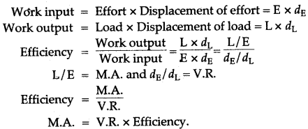
Question 4: What is efficiency of a machine? Establish a relation between efficiency, M.A. and V.R.
Answer: The ratio between work output and work input is called efficiency.
![]()
Relation between, M.A., V.R. and Efficiency: Let a machine overcome a load L by applying an effort E. In time t, the displacement of effort is dE and displacement of load is dL. Then
Question 5: What is the relation between the mechanical advantage and the number of strands of string used to support the load, in a ‘block and tackle’ set-up?
Answer: The mechanical advantage is equal to the number of strands of string, used to support the load, only if the ‘block and tackle set up’ can be assumed to be ideal (absence of friction, etc.) and the lower blocks of pulleys have a negligible weight. Both these conditions cannot be satisfied in actual practice. Hence, in practical situations, the M.A. of a ‘block and tackle set up’ is always less than fire number of strands of string used to support the load.
Question 6: Shears, used for cutting metals and scissors used for cutting clothes are both examples of levers of first order. However, whereas the shears always have short blades and long handles, the scissors often have blades much longer than the handles. Explain, why this is so?
Answer: The mechanical advantage of an (ideal) liver equals the ratio between-the effort arm to the load arm.
For the shears (used for cutting metals), the ‘load’ is really a formidable one. Therefore, we need a large mechanical advantage to keep the applied effort with in reasonable limits. To ensure this, the shears are made to have short blades (small load arm) and long handles (long effort arm).
For the scissors (used for cutting clothes), the ‘load’ is an almost negligible one. Mechanical advantage, therefore, here may be more or less than one. The scissors, therefore, often have blades much longer than the handles.
Question 7: The following are example of levers. State the class of lever to which each one belongs giving the relative positions of Load (L), Effort (E), Fulcrum (F):
(i) Scissors (ii) Sugar tongs (iii) Nut cracker (iv) Pliers.
Answer:
| Name of Lever | Lever Class | Fulcrum | Position of Effort | Load | |
| (i) | Scissors | First | At centre | One end | Other end |
| (ii) | Sugar tongs | Third | One end | At centre | Other end |
| (iii) | Nut cracker | Second | One end | Other end | At centre |
| (iv) | Pliers | First | At centre | One end | Other end |
Question 8: What is a block and tackle system of pulleys? What precautions would you observe while rounding the string so that the effort is applied in the downward direction?
Answer: A block and tackle system of pulleys consists of two blocks of pulleys, each block having one or more than one pulleys. The upper block of pulleys is fixed to a rigid support and the lower block of pulleys is movable. The number of pulleys in the movable block is either equal or one less than the number of pulleys in the fixed block.
While rounding the string, its one end is attached to the hook of movable block if the number of pulleys in the fixed block is more than that in the movable block or to the hook of the fixed block if the number of pulleys is the same in both the blocks.
Figure Based Short Answers
Question 1: A crowbar, of Length 120 cm has its fulcrum situated at a distance of 20 cm from the load. Calculate the mechanical advantage of the crow bar.
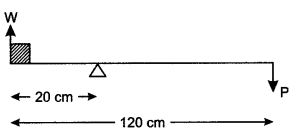
Answer: By the principle of moments.
Moments of load about the fulcrum = Moment of efforts about the fulcrum

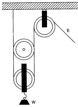
Question 2: In the alongside figure of two pulleys shown a system in which one pulley is fixed and the other is movable. What is the velocity ratio of the system?
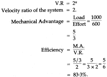
An effort of 600 N is needed to lift a weight of 1000 N. What are the mechanical advantage and efficiency of the pulley system?
Answer: If there are n movable pulleys connected to a fixed pulley, then velocity ratio is
Question 3: Draw a labelled sketch of a class II lever. Give one example of such a lever.
Answer: A labelled diagram of a class II lever is given below. Its example is a nut-cracker.
IL(Load)
Second Class Lever

Question 4: In the diagram shown alongside of a claw hammer, mark the fulcrum (F) and indicate the directions of load (L) and effort (E) with arrows. What class of lever is it? Give one more example of this class of lever.
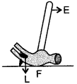
Answer: Claw-hammer is the lever of first order. One more example of this class of lever is see-saw. In the following diagram, F indicates the position of fulcrum. The arrows labelled L and E respectively indicate the directions of load and effort.
Question 5: In the following diagram of a wheel barrow, mark the fulcrum (F) and indicate the directions of load (L) and effort (E) with arrows.
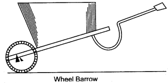
What class of lever is it? Give one more example of the same class of lever.
Answer: In the diagram given below F shows the position of fulcrum and arrows marked at L and E indicate the direction of load and effort respectively.
It belongs to class II liver.
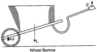
A nut cracker is one more example of same class of lever.
Question 6: When we want to use a machine as a force multiplier, which class of lever should we preferably use? Give a simple diagram of such a lever.
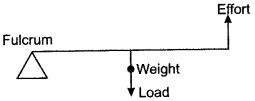
Answer: Though we can use either levers of class I or class II, for multiplying force, we should preferably use a lever of class II. This is because the mechanical advantage of levers of class II, is always greater than one. A simple diagram of a lever of class II is shown alongside. The wheel barrow, the bottle opener and the mango cutter are some of the practical forms of lever of class II.
Question 7: The diagram below shows a lever in use.
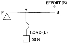
(i) To which class of lever does it belong?
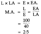
(ii) If FA = 40 cm, AB = 60 cm, then find the mechanical advantage of the lever.
Solution: (i) Class 2 lever.
(ii) We know,
Question 8: What is a pulley?
Answer:
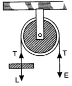
A pulley is an example of a simple type of machine. It is either a wooden or a metallic disc which can rotate about a horizontal axis passing through its centre. It has a grooved rim along which a rope or chain can slide. It is generally mounted in a frame work called a block.
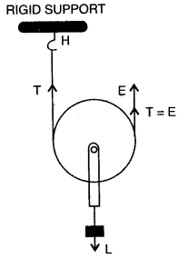
Question 9: Name the type of single pulley that can act as a force multiplier. Draw a labelled diagram of the above named pulley.
Answer: Single Movable Pulley
Question 10: Draw a diagram to show how a single pulley can be used so as to have its ideal M. A. = 2.
Solution:
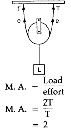
Figure Based Long Answers
Question 1: (i) Calculate the mecahnical advantage of the lever shown in figure.
(ii) How do you define mechanical advantage of a machine?

Answer:

Question 2: A uniform metre scale is kept in equilibrium when supported at the 60 cm mark and a mass M is suspended from the 90 cm mark as shown in the figure. State with reasons, whether the weight of the scale is greater than, less than or equal to the weight of mass M.

Answer: Let M be load.
∴ Load arm = 90 – 60 = 30 cm
Since wt. of scale will act at centre of gravity of scale which is the midpoint of the scale.
∴ Effort arm = 60 – 50 = 10 cm
Let wt. of scale be W
By principal of moments L × dL = E × dE
M × 30 = W × 10
W = 3M
∴ Since weight of scale is three times that of M.
∴ Weight of scale is greater than weight of M.
Question 3: What is a lever?
Answer:

A lever is a special case of the application of the law of moments. It is a rigid bar, straight or bent, which is capable of rotation about a fixed point or a fixed line, called axis of rotation. This fixed point or the axis of rotation is called the fulcrum. An effort E is applied at the point A of the lever to overcome a resistance (or load) at another point B, as shown in the diagram.
Question 4: The diagram shows the use of a lever.
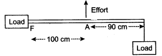
(i) State the principle of moments as applied to the above lever.
(ii) Which class of lever is this? Give an example of this class of lever.
(iii) If FA = 100 cm, AB = 90 cm, calculate the minimum effort required to lift the load.
Solution: (i) Sum of the clockwise moments about the fulcrum is equal to the sum of the anti-clockwise moments about the fulcrum.
(ii) Lever of class III, example: foreceps or a pair of tongs.
(iii) E × 100 = 190 × 20
∴ E = 38 N.
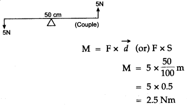
Question 5: Two forces each of 5N act vertically upwards and downwards respectively on the two ends of a uniform metre rule which is placed at its mid-point as shown in the diagram. Determine the magnitude of the resultant moment of these forces about the midpoint.
Solution:
Question 6: State the types (or kinds) of lever, and give two examples of each kind.
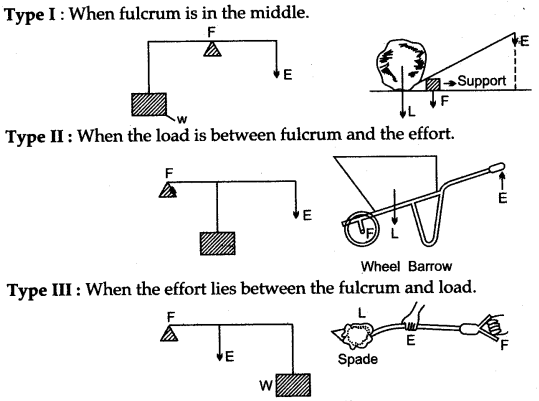
Answer: There are three kinds of lever, depending upon the different positions of the load, fulcrum and the effort.
Question 7: Draw the diagram of a single movable pulley and obtain its mechanical advantage, velocity ratio and efficiency.
Answer: Since it is inconvenient to apply the effort in an upward direction, a single fixed pulley is used to change the direction of effort.
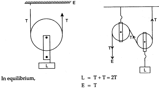

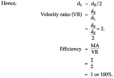
As the effort is pulled down through a distance dE, the two segments of the thread carrying the movable pulley and the load goes up by dE/2.
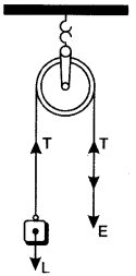
Question 8: Draw diagram of a single fixed pulley and obtain expressions for its:
(i) Mechanical advantage, (ii) Velocity ratio, and (iii) Efficiency, in the ideal case.
Answer: The diagram of a single fixed pulley is shown alongside. If T is the tension in each strand of the string and in the ideal case string is massless and there is no friction in the pulley bearings, then in equilibrium, E = T and L = T

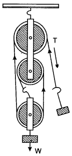
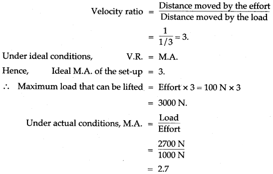
Question 9: The pulley system shown in the figure is to be used to lift a load W. If the man applying the effort cannot apply a force exceeding 1000 N, what is the maximum load that can be lifted?
The actual load that the man is finally able to lift turns out to be 2700 N. What are the values of the actual M.A., obtained and the efficiency of the actual set-up?
Solution: The load lifted would be a maximum when conditions are ideal. Since this set-up uses three strands of string, the load gets raised only through 1/3rd of the distance through which the effort moves.
 Hence,

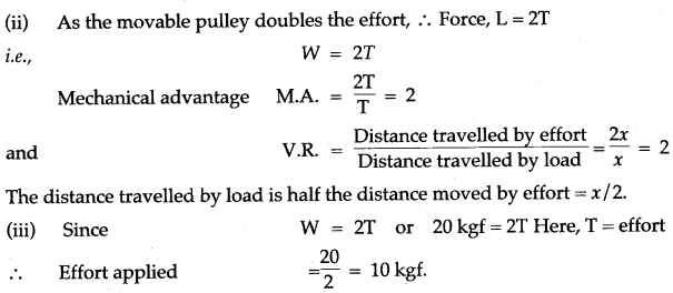
Question 10: The alongside figure shows the combination of a movable pulley P1 with a fixed pulley P2 used for lifting up a load W.
(i) State the function of the fixed pulley P2.
(ii) If the free end of the string moves through a distance x, find the distance by which the load W is raised.
(iii) Calculate the force to be applied at C to just raise the load W = 20 kgf, neglecting the weight of the pulley P1 and friction.
Solution: (i) It is quite difficult to apply effort in the upward direction, if no fixed pulley P2 is used. The fixed pulley changes the direction of effort from upwards to downwards, making the application of the effort more convenient and easier.
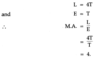
Question 11: Draw a diagram showing a block and tackle system of 4 pulleys.

(i) State, how many strands of tackle support the load?
(ii) Draw arrows to represent tension in each strand.
(iii) Find the mechanical advantage of the system, stating the assumptions made.
(iv) If load is pulled up by a distance 1m, how much does the effort end move?
Solution: The adjacent diagram shows a block and tackle system of 4 pulleys.
(i) Four strands of tackle support the load.
(ii) The tension in each strand is shown by the arrow marked as T.
(iii) If we neglect the friction of the pulleys and weight of the pulleys in the lower block, then:
(iv) If load is pulled up by a distance 1m, the effort end moves by 4 m.
Question 12: A block and tackle system of pulleys has a velocity ratio 4.
(i) Draw a labelled diagram of the system indicating clearly the points of application and directions of load and effort.
(ii) What is the value of the mechanical advantage of the given pulley system if it is an ideal pulley system?
Answer:
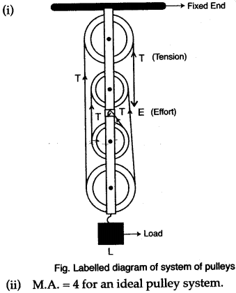
Question 13: Diagram given below, shows an arrangement of four pulleys. A load L is attached to the movable lower block and effort E is applied at free end of the string.
Copy the diagram; and
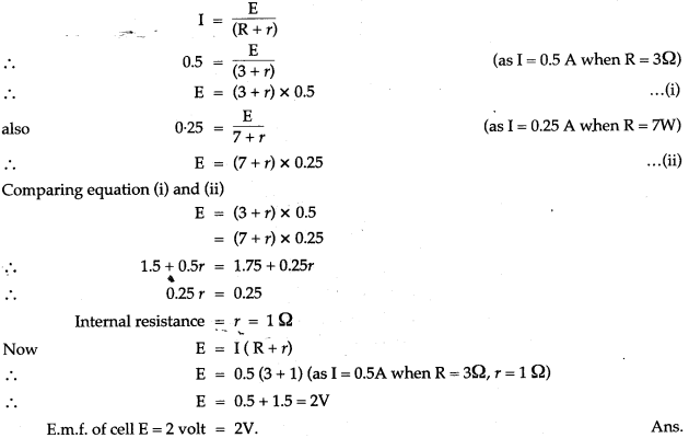
(i) Draw arrows to indicate tension in each part of the string; and
(ii) Calculate the mechanical advantage of the system.
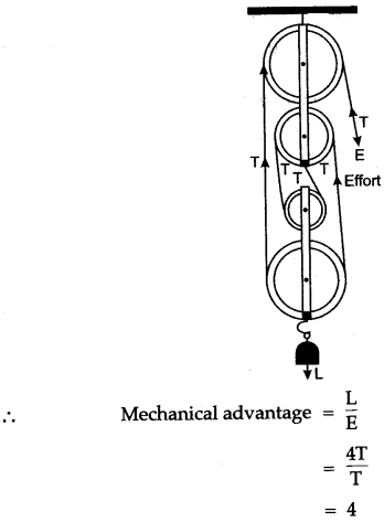
Solution: The following diagram shows a block and tackle system of 4 pulleys.
(i) The tension in each string is shown by the arrow marked as T.
(ii) If we neglect the friction of the pulleys and weight of the pulleys in the lower block, then
L = 4T and E = T
Short Numericals
Question 1: The length of a nut-cracker is 12 cm. A nut when kept at a distance of 4 cm from its fulcrum requires an effort of 100 gf to crack it. What force will be required to crack the nut without using the nut-cracker?
Solution:

Thus, a force of 300 gf is required to crack the nut without using the nut cracker.
Question 2: A crow bar of length 100 cm is used to lift a load of 5 kgf. It has its fulcrum at a distance of 20 cm from the load. Calculate: (i) the mechanical advantage of crow bar, and ii) the effort applied at the other end.
Solution: Given: L = 5 kgf, Load arm = 20 cm, Effort arm = 100 – 20 = 80 cm.
(Since the crow bar is the lever of first order with fulcrum in between the load and the effort).
![]()

Question 3: In a single movable pulley system, a load of 125 kgf is lifted by an effort of 75 kgf. Find the percentage efficiency of system.
Solution:

Question 4: A woman draws water from a well using a fixed pulley. The mass of the bucket and water together is 60 kg. The force applied by the woman is 70 N. Calculate the mechanical advantage. [Take g = 10 m/s2].
Solution:

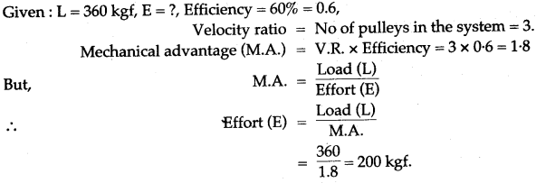
Question 5: A man raises a load of 360 kgf using a block and tackle system of 3 pulleys. If the efficiency of the pulley system is 60%, what effort is applied by the man?
Solution:
Long Numericals
Question 1: A machine is driven by a 50 kg mass falling at a rate of 10.0 m in 5s. It lifts n load of 250 kgf. Taking the force of gravity on 1 kg mass as 10 N. Calculate the power input to the machine. If the efficiency of the machine is 60%, find the height to which the load is raised in 5s.
Solution:
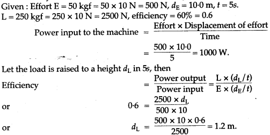
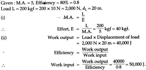
Question 2: The mechanical advantage of a machine is 5 and its efficiency is 80%. It is used to lift a load of 200 kgf to a height of 20 m. Calculate:
(i) The effort required, and
(ii) The work done on the machine (g = 10 ms-2).
Solution:
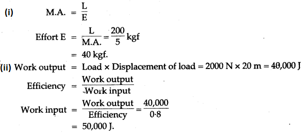
Question 3: The mechanical advantage of a machine is 5 and its efficiency is 80%. It is used to lift a load of 200 kgf to height of 20m. Calculate: (i) the effort required, and (ii) the work done on the machine, (g = 10 ms-2)
Solution: Given: M.A. = 5, Efficiency = 80% = 0.8, Load, L = 200 kgf = 200 × 10N = 2000 N, d1 = 20 m.
Question 4: A cook used a ‘fire tong pair’ of length 32 cm. to lift a piece of burning coal of mass 500 g. If he applies his effort at a distance of 8 cm from the fulcrum, what is his effort? Assume friction etc. to be absent. Also obtain values of the M.A. and the V.R. of this ‘machine’.
Solution: The ‘fire tong pair’ is a lever of class III in which the point of application of the effort is in between the load and the fulcrum. Hence, when friction, etc., are assumed absent, we have:

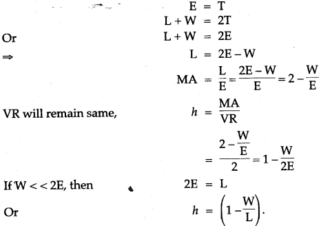
Question 5: If weight of the movable pulley is W, obtain the expression for MA, VR and efficiency.
Solution: If weight of the movable pulley with its frame is W, in equilibrium
Question 6: A simple machine enables us to lift a load of 10,000 N by the application of an effort of 500 N. However, when the point of application of the effort moves through 2.5 m, the load gets raised through 10 cm only. What are the values of the: (i) M.A. (ii) V.R. and (iii) Efficiency of the machine?
Solution:

Question 7: A pulley system has a velocity ratio of 4 and an efficiency of 90%. Calculate:
(i) the mechanical advantage of the system.
(ii) the effort required to raise a load of 300 N by the system.
Solution:
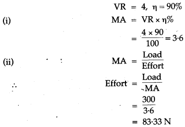
Question 8: A ‘block and tackle’ system used 3 pulleys in the lower block and 4 pulleys in the upper block. What is the ‘velocity ratio’ of this system? If the load is to be lifted by a person capable of applying a maximum effort of 1000 N, what is the maximum load than can be lifted under ideal conditions?
The actual maximum load that gets lifted turns out to be 6300 N. What are the values of the actual M.A. and efficiency of the set-up?
Solution: There being 7 pulleys in all, the load is supported by 7 strands of string. Hence it gets lifted only through 1/7 th of the distance through which the effort is applied. Hence velocity ratio of the setup has a value 7.
Under ideal conditions, M.A. = V.R. = 7
Hence, the maximum load that can be lifted under ideal conditions is:
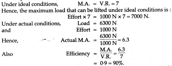
Question 9: A boy lifts a load of 40 kgf through a vertical height of 2m in 5s by using a single fixed pulley when he applies an effort of 48 kgf. Calculate: (i) the mechanical advantage, and (ii) the efficiency of the pulley. Why is the efficiency of the pulley is not 100%? (iii) the energy gained by the load in 5s, and (iv) the power developed by the boy in raising the load.
Solution:

(ii) If the effort moves a distance d downwards, the load also moves a distance d upwards. So velocity ratio (V.R.) = d/d = 1,
![]()
The efficiency of the pulley is not 100% because some energy is wasted in overcoming the friction in the pulley bearings.

For More Resources
