Plus Two Physics Notes Chapter 10 Wave Optic is part of Plus Two Physics Notes. Here we have given Plus Two Physics Notes Chapter 10 Wave Optic.
| Board | SCERT, Kerala |
| Text Book | NCERT Based |
| Class | Plus Two |
| Subject | Physics Notes |
| Chapter | Chapter 10 |
| Chapter Name | Wave Optic |
| Category | Plus Two Kerala |
Kerala Plus Two Physics Notes Chapter 10 Wave Optic
Introduction
In 1678, the Dutch physicist Christian Huygens put forward the wave theory of light. We will discuss in this chapter.
Wavefront:
The wavefront is defined as the locus of all points which have the same phase of vibration. The rays of light are normal to the wavefront. Wavefront can be divided into 3.
- Spherical wavefront
- Cylindrical wavefront
- Plane wavefront.
1. Spherical Wavefront:
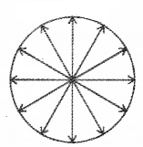
The wavefront originating from a point source is spherical wavefront.
2. Cylindrical Wavefront:
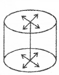
If the source is linear, the wavefront is cylindrical.
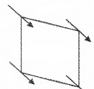
3. Plane wavefront:
If the source is at infinity, we get plane wavefront.
Huygen’s Principle
According to Huygen’s principle
- Every point in a wavefront acts as a source of secondary wavelets.
- The secondary wavelets travel with the same velocity as the original value.
- The envelope of all these secondary wavelets gives a new wavefront.
Refraction And Reflection Of Plane Waves Using Huygens Principle
1. Refraction of a plane wave. (To prove Snell’s law):
AB is the incident wavefront and c1 is the velocity of the wavefront in the first medium. CD is the refracted wavefront and c2 is the velocity of the wavefront in the second medium. AC is a plane separating the two media.
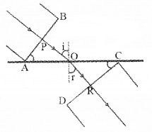
The time taken for the ray to travel from P to R is
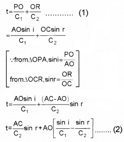
O is an arbitrary point. Hence AO is a variable. But the time to travel a wavefront from AB to CD is constant. In order to satisfy this condition, the term containing AO in eq.(2) should be zero.
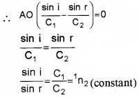
where 1n2 is the refractive index of the second medium w.r.t. the first. This is the law of refraction.
2. Reflection of plane wave by a plane surface:
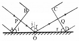
AB is the incident wavefront and CD is the reflected wavefront, ‘i’ is the angle of incidence and ‘r’ is the angle of reflection. Let c1 be the velocity of light in the medium. Let PO be the incident ray and OQ be the reflected ray.
The time taken for the ray to travel from P to Q is
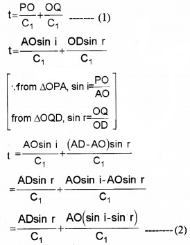
O is an arbitrary point. Hence AO is a variable. But the time to travel for a wave front from AB to CD is a constant. So eq.(2) should be independent of AO. i.e., the term containing AO in eq.(2) should be zero. AO
∴ \(\frac{A O}{C_{1}}\)(sin i – sin r) = 0
sin i – sin r= 0
sin i = sin r
i = r
This is the law of reflection.
Behavior of wave frond as they undergo refraction or reflection.
a. Wave frond through the prism:
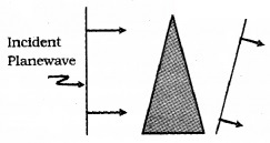
Consider a plane wave passing through a thin prism. The speed of light waves is less in glass. Hence the lower portion of the incoming wave frond will get delayed. So outgoing wavefrond will be tilted as shown in the figure.
b. Wave frond through a thin convex lens:
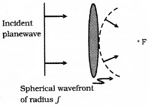
Consider a plane wave passing through a thin convex lens. The central part of the incident plane wave travels through the thickest portion of lens.
Hence central part get delayed. As a result the emerging wavefrond has a depression at the centre. Therefore the wave front becomes spherical and converges to a point F.
c. Plane wave incident on a concave mirror:
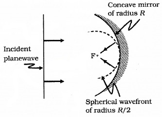
A plane wave is incident on a concave mirror and on reflection we have spherical wave converging to the focul point F.
3. The Doppler Effect:
There is an apparent change in the frequency of light when the source or observer moves with respect to one another. This phenomenon is known as Doppler effect in light.
When the source moves away from the observer the wavelength as measured by the source will be larger. The increase in wavelength due to Doppler effect is called as red shift.
When waves are received from a source moving towards the observer, there is an apparent decrease in wavelength, this is referred to as blue shift.
Mathematical expression for Doppler shift:
The Doppler shift can be expressed as

Vradial is the component of source velocity along the line joining the observer to the source.
Coherent And Incoherent Addition Of Waves
Superposition principle:
According to the superposition principle, the resultant displacement produced by a number of waves at a particular point in the medium is the vector sum of the displacements produced by each of the waves.
Coherent sources:
Two sources are said to be coherent, if the phase difference between the displacements produced by each of the waves does not change with time.
Incoherent sources:
Two sources are said to be coherent, if the phase difference between the displacements produced by each of the waves changes with time.
Constructive interference:
Consider two light waves meet together at a point. If we get maximum displacement at the point of meeting, we call it as constructive interference.
Destructive interference:
Consider two lightwaves meet together at a point. If we get minimum displacement at the point of meeting, we call it as destructive interference.
Mathematical condition for Constructive interference and Destructive interference:
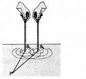
Consider two sources S1 and S2. Let P be point in the region of s1 and s2. The displacement produced by the source s1 at P.
y1 = a cos ωt
Similarly, the displacement produced by the source s2 at P
y2 = a cos (ωt + Φ)
Where Φ is the phase difference between the displacements produced by s1 and s2
The resultant displacement at P,
Y = y1 + y2
= a cos ωt + a cos (ωt + Φ)
= a (cos ωt + cos (ωt + Φ))
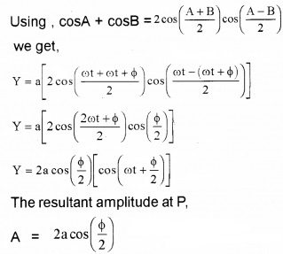
Therefore total intensity at P,
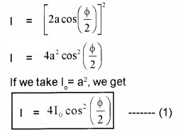
Constructive interference:
If we take phase difference Φ = 0, ±2π, ±4π……., we get maximum intensity (4I0) at P. This is the mathematical condition for constructive interference. The condition for constructive interference can be written in the form of path difference between two waves.
![]()
Where n = 0, 1, 2, 3……..
Destructive interference:
If we take phase difference Φ = ±π, ±3π, ±5π………., we get zero intensity at P. This is the mathematical condition for destructive interference. The condition for destructive interference can be written in the form of path difference between two waves.
![]()
Where n = 0, 1, 2, 3……..
Interference Of Light Waves And Youngs Double Slit Experiment
Young’s double-slit experiment:
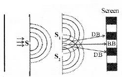
The experiment consists of a slit ‘S’. A monochromatic light illuminates this slit. S1 and S2 are two slits in front of the slit ‘S’. A screen is placed at a suitable distance from S1 and S2. Light from S1 and S2 falls on the screen. On the screen interference bands can be seen.
Explanation:
If crests (ortroughs) from S1 and S2 meet at certain points on the screen, the interference of these points will be constructive and we get bright bands on the screen.
At certain points on the screen, crest and trough meet together. Destructive interference takes place at those points. So we get dark bands.
Expression for band width:
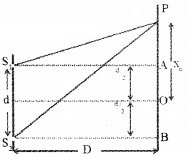
S1 and S2 are two coherent sources having wave length λ. Let ‘d’ be the distance between two coherent sources. A screen is placed at a distance D from sources. ‘O’ is a point on the screen equidistant from S1 and S2.
Hence the path difference, S1O – S2O = 0
So at ‘O’ maximum brightness is obtained.
Let ‘P’ be the position of nth bright band at a distance xn from O. Draw S1A and S2B as shown in figure. From the right angle ∆S1AP
we get, S1P2 = S1A2 + AP2
S1P2 = D2 + (Xn – d/2)2 = D2 + Xn2 – Xnd + \(\frac{d^{4}}{4}\)
Similarly from ∆S2BP we get,
S2P2 = S2B2 + BP2
S2P2 = D2 + (Xn + d/2)2
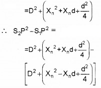
S2P2 – S1P2 = 2xnd
(S2P + S1P)(S2P – S1P) = 2xnd
But S1P ≈ S2P ≈ D
∴ 2D(S2P – S1P) = 2xnd
i.e., path difference S2P – S1P = \(\frac{x_{n} d}{D}\) ____(1)
But we know constructive interference takes place at P, So we can take
(S2P – S1P) = nλ
Hence eq(1) can be written as

Let xn+1 be the distance of (n+1)th bright band from centre o, then we can write
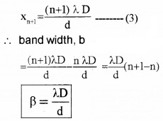
This is the width of the bright band. It is the same for the dark band also.
Diffraction
The bending of light round the comers of the obstacles is called diffraction of light.
1. The single slit diffraction:
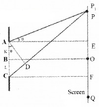
Consider a single slit AC having length ‘a’. A screen is placed at suitable distance from slit. B is midpoint of slit, A straight line through B (perpendicular to the plane of slit), meets the screen at O. AD is perpendicular CP.
Calculation of path difference:
Consider a point P on the screen having a angle θ with normal AE. The path difference between the rays (coming from the bottom and top of the slit) reaching at P,
CP – AP = CD
(CP – AP) = a sin θ
path difference, (CP – AP) = a θ______(1)
[for small θ. sin θ ≈ θ]
(I) Position of maximum intensity:
Consider the point ‘O’, the path difference between the rays (coming from AB and BC) reaching at O is zero. Hence constructive interference takes place at ‘O’. Thus maximum intensity is obtained. This point is called central maximum or the principal maximum.
(II) Position of secondary minima:
Let P be a point on the screen such that the path difference between the rays AP and CP be λ.
ie, CP – AP = λ______(2)
Substituting eq (1) in eq (2) we get
θ = λ
(or) θ = \(\frac{\lambda}{a}\)______(3)
Let the slit AC be imagined to be split into two equal halves AB and BC. For every point in AB, there is a corresponding point in BC such hat the distance between the points are equal to a/2 Consider two points K and L such that, KL = a/2. There fore, the path difference between the rays (coming form K and L) at P is,.
LP – KP = \(\frac{a}{2}\)θ_______(4)
Substituting (3) in (4) we get

This means that the rays (coming from K and L) reaching at P are out of phase and cancel each other. Hence the intensity at P becomes zero.
In otherwards, at angle θ = \(\frac{\lambda}{\mathrm{a}}\)
The intensity becomes zero.
Similarly on the lower half of the screen, the intensity is zero for which θ = – \(\frac{\lambda}{\mathrm{a}}\)
The general equation for zero intensity can be written as
θ = \(\pm \frac{n \lambda}{a}\)
Where n = 1, 2, 3,…
For first minima n = 1, and second minima n = 2.
(III) Position of Secondary maxima:
Let P be a point on the screen, such that
CP – AP = \(\frac{3}{2}\)λ
From eq (1),we know (CP – AP) = aθ
Therefore aθ = \(\frac{3}{2}\)λ
The wave front AC can be divided into three equal parts.
The rays from first and second parts will cancel each other and the rays from third part will reach at P. Hence the point P becomes bright.
Similarly the next maximum occurs at θ = \(\frac{5}{2}\)\(\frac{λ}{a}\)
The general equation for maximum can be written
\(\theta=\pm \frac{(2 n+1) \lambda}{2 a}\)
1. (a) Intensity Distribution on the screen of diffraction pattern:
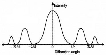
(b) Comparison between interference and diffraction bands:
Interference:
- Interference is due to superposition of waves coming from two wavefronts.
- Interference bands are of equal width.
- Minimum intensity regions are perfectly dark.
- All the bright bands are of equal intensity.
Diffraction:
- Diffraction is due to the superposition of waves coming from different parts of the same wave front.
- Diffraction bands are of unequal width.
- Minimum intensity regions are not perfectly dark.
- All bright bands are not of the same intensity.
2. Seeing The Single Slit Diffraction Pattern:
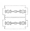
Take two razor blades and an electric bulb. Hold the two blades as shown in the figure. Observe the glowing bulb through the slit. A diffraction pattern can be seen.
3. Resolving Power Of Optical Instruments:
Resolving power of optical instrument:
The ability of an optical instrument to form distinctly separate images of the two closely placed objects is called is resolving power.
Explanation:
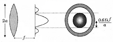
The image of a point object formed by an ideal lens is a point only. But because of diffraction effect, instead of point image, we get a diffraction pattern. Diffraction pattern consists of a bright central circular region surrounded by concentric dark and light rings.
Let us discuss three cases; when we observe two-point object through a lens.
1. Unresolved:
If central maxima of two diffraction pattern are overlapped, the image is unresolved. This image can’t be viewed clearly.
2. Just resolved:
If central maxima of two diffraction pattern are just separated, the image is just resolved. In this case image is just distinqushed.
3. Resolved:
If central maxima of two diffraction pattern are separated, the image is resolved. This image can be viewed clearly.
Limit of resolving power of optical instrument:
The minimum distance of separation between two points so that they are just resolved by the optical instrument is known as its limit of resolution. Resolving power is also defined as reciprocal of limit of resolution.

1. Telescope and resolving power:
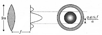
Telescope consist of two convex lenses called eyepiece and objective .The light falling on objective lens undergoes for diffraction. Hence a diffraction pattern of bright and dark rings is produced around central bright region as shown in figure.
The radius of central bright region,

This radius can be written in terms of angular width,
∆θ ≈ \(\frac{0.61 \lambda}{\mathrm{a}}\)
Where a is the radius and f – focal length of objective lens. λ is the wave length of light used.
This angular width of central bright region is related to resolving power of telescope. When angular width of spot increases, resolving power decreases.

The limit of resolution of telescope, ∆θ ≈ \(\frac{0.61 \lambda}{\mathrm{a}}\)
This equation shows that telescope will have better resolving power if ‘a’ is large and λ is small.
2. Microscope and resolving power:
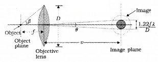
In microscope the object (microscopic size) is placed slightly beyond f (focal length of objective lens). When the separation between two points in a microscopic specimen is comparable to the wavelength λ of light, the diffraction effect become important.

Where nsinβ is called numerical aperture, n is the refractive index of liquid used in microscope, β is the half angle of the cone of light from the microscopic object with objective lens.
The limit of resolution of microscope dmin = \(\frac{1.22 f \lambda}{2 n \sin \beta}\)
This equation also can be written as dmin = \(\frac{1.22 \lambda}{2 \tan \beta}\)
Note: Telescope is used to resolve objects at far distance but microscope is used to produce magnification of near objects.
4. The Validity Of Ray Optics:
Fresnel distance is the distance beyond which the diffraction properties becomes significant, (ie. the ray optics is converted into wave optics).
Fresnel distance, zF = \(\frac{\mathrm{a}^{2}}{\lambda}\)
Where ‘a’ is the size of the aperture
For distances much smaller than zF, the spreading due to diffraction is smaller compared to the size of the beam. It becomes comparable when the distance is approximately zF. For distances much greater than zF, the spreading due to diffraction dominates over that due to ray optics.
Polarisation
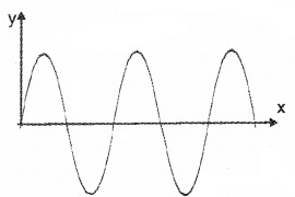
Consider a long string that is held horizontally, the other end of which is assumed to be fixed. If we move the end of the string up and down in a periodic manner, a wave will propagate in the +xdirection (see above figure). Such a wave can be described by the following equation
y(x,t) = a sin (kx – ωt)
where ‘a’ represent the amplitude and k = 2π/λ represents the wavelength associated with the wave.
Since the displacement (which is along the y-direction) is at right angles to the direction of propagation of the wave, this wave is known as a transverse wave.
Also, since the displacement is in the/direction, it is often called to as a y-polarised wave. Since each point on the string moves on a straight line, the wave is also called to as a linearly polarised wave.
The string always remains confined to the x-y plane and therefore it is also called to as a plane polarised wave.
In a similar manner we can consider the vibration of the string in the x-z plane generating a z-polarised wave whose displacement will be given by
z(x,t) = a sin (kx – ωt)
Unpolorised wave:
If the plane of vibration of the string is changed randomly in very short intervals of time, then it is known as an unpolarized wave.
(a) Polarization property of light:
When light passes through certain crystals like tourmaline, the vibrations of electric field vector are restricted. This property exhibited by light is known as polarization.
Note:
- Polarization is the property of light which reveals that light is a transverse wave.
- A sound wave can’t be polarized because sound wave is a longitudinal wave.
Polarizer and analyzer:
When an unpolarized light passes through a tourmaline crystal T1, the light coming out of T1 is plane polarized.
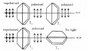
In order to check the polarization, another tourmaline crystal T2 is kept parallel to T1.
When we look through T2 we get maximum intensity. Then T2 is rotated through 90°. If no light is coming, we can say that light from T1 is plane polarized.
Polarizer: The crystal which produces polarized light is known as polarizer.
Analyzer: The crystal which is used to check weather the light is polarized or not is called the analyzer or detector.
Law of Malus: This law states that when a beam of plane polarized light is incident on an analyzer, the intensity (I) of the emergent light is directly proportional to the square of the cosine of the angle (θ) between the polarizing directions of the polarizer and the analyzer.
![]()
I = Im cos2θ
where Im is the maximum intensity.
1. Polarisation By Scattering:
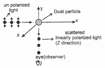
The nunpolarized light incident on a dust particle in atmosphere, it is absorbed by electrons in the dust particle. The electrons in the dust particle reradiate light in all directions. This phenomenon is called scattering.
Explanation:
Let a beam of unpolarized light be incident on a dust particle along x-axis. The electrons in the dust particle absorb light and behave as a oscillating dipole. This dipole emit light in all directions.
When an observer observe this particle along y-axis, the observer can receive light from the electron vibrating in z-axis. This light is linearly polarised in z-direction (its plane of polarisation is yz).
This polarised light is represented by dots in the picture. This explains the polarisation of scattered light from the sky.
2. Polarization By Reflection:
At a particular angle of incidence on a medium, the reflected lights is fully polarized. This angle is known as polarizing angle or Brewster’s angle. At polarizing angle, the reflected and refracted rays are mutually perpendicular.
Brewster’s law:
Brewster’s law states that the tangent of the polarizing angle is equal to the refractive index of the material of the reflector.
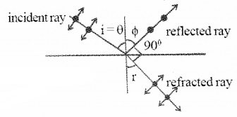
Let ‘Q ’ be the polarizing angle and ‘n’ be the refractive index of the medium then,
tan θ = n
At polarizing angle, r + θ =90°.
Proof:
Consider an unpolarized light coming from air and is incident on a medium having refractive index n. Let θ be the angle of incidence, Φ be the angle of reflection and ‘r’ be the angle of refraction.
Using snells law, we can write
n = \(=\frac{\sin \theta}{\sin r}\) ______(1)
At the polarizing angle reflected and refracted light are mutually perpendicular
ie. Φ – 90 + r = 180°
∴ r = 90 – Φ______(2)
Substituting eq (2) in eq(1), we get

But we know
Angle of incidence (θ) = angle of reflection(Φ)
∴ n = \(\frac{\sin \theta}{\cos \theta}\)
n = tanθ
We hope the Plus Two Physics Notes Chapter 10 Wave Optic help you. If you have any query regarding Plus Two Physics Notes Chapter 10 Wave Optic, drop a comment below and we will get back to you at the earliest.
