What do you mean by rectification?
Diode as a Rectifier:
- A rectifier is a device that converts alternating current to direct current.
- It consists of one or more semiconductor devices or vacuum tubes.
- Diodes are widely used as a rectifier.
- Rectification is a process of converting alternating current into direct current by using a diode.
What is a half wave rectifier?
Half-wave Rectification:
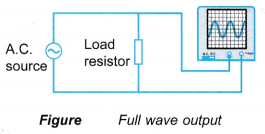
- If an alternating current is connected in series with a load resistor, the voltage across the load resistor varies. By connecting the Y-input and earth terminals of the C.R.O. parallel across the load resistor as shown in Figure, a full alternating voltage wave form is seen on the screen. This is when there is no rectification.
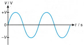
- Figure shows the graph of output voltage against time for no rectification.
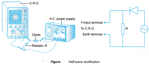
- When a diode is connected in. series with the load resistor, any current that passes through the resistor must also pass through the diode.
- Since the diode allows current to flow in one direction, therefore, the current will only flow in the first half-cycle when the diode is forward bias.
- The current is blocked in the second half-cycle when the diode is reverse bias. Thus, the current flowing in the circuit is said to be half-wave rectified.
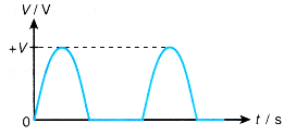
- In the half-wave rectification, the rectified current is a series of pulses as shown in Figure.
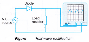
- Half-wave rectification is a process where only half of every cycle of an alternating current is made to flow in one direction only. Figure shows the graph of output voltage against time for half-wave rectification.
- A half-wave rectifier is also called a clipper since it clips half of the wave cycle. So, only half of the input wave form becomes the output. Flence, it is very inefficient if it is used for power transfer.
People also ask
- Understanding Semiconductor Diodes
- What do you mean by logic gates?
- What is meant by combinational logic circuits?
- What is the use of transistor in electronics?
- What is the basic function of a transistor?
- How does a transistor works as an amplifier?
- How can a transistor be used as a switch?
What is a full wave rectifier used for?
Full-wave Rectification:
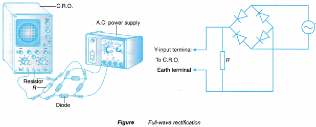
- When four diodes are connected as shown in Figure, the circuit is called a bridge rectifier.
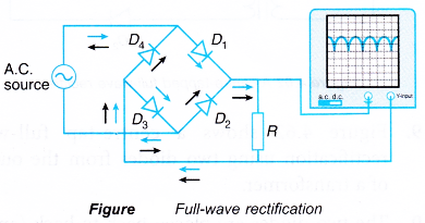
- Each pair of the diodes allows current to flow on alternate half-cycles.
- In the first half-cycle, diodes D1 and D3 are in forward bias while diodes D2 and D4 are in reverse bias.
- So, current flows through diodes D1 and D3 The direction of the current flow is shown by the coloured arrows in Figure.
- In the second half-cycle, diodes D2 and D4 are in forward bias while D1 and D3 are in reverse bias.
- So, current flows through diodes D2 and D4. The direction of the current flow is shown by the black arrows in Figure.
- Hence, in a full-wave rectification, the current flow is continuous.
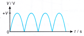
- Full-wave rectification is a process where both halves of every cycle of an alternating current is made to flow in the same direction. Figure shows the graph of output voltage against time for a full-wave rectification.
- Figure shows a centre-tap full-wave rectification using two diodes from the output of a transformer.
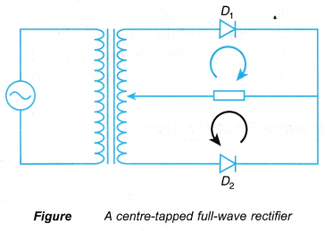
- The two diodes are placed back to back (anode to anode or cathode to cathode) and connected to the centre-tapped secondary coil.
- In the first half-cycle, the upper terminal will be positive, relative to the centre tap. Meanwhile the lower terminal will be negative, relative to the centre tap.
- So, diode D1 is in forward bias and diode D2 is in reverse bias. The current flow is represented by the coloured arrow.
- In the second half-cycle, the a.c. will be generated in the opposite way as in the first half-cycle. Therefore, diode D2 is in forward bias and diode D1 is in reverse bias. The current flow is represented by the black arrow.
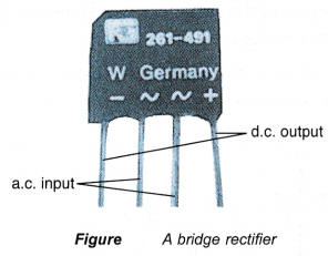
- A practical bridge rectifier has four terminals, two input terminals from the a.c. supply marked ~ and two output terminals marked + and – which supply direct current. These symbols are usually marked on a bridge rectifier as shown in Figure.
What is meant by smoothing capacitor?
Capacitor Smoothing
- Both half-wave and full-wave rectifications do not provide a steady direct current like the battery. To provide a uniform d.c. output, the varying rectified output needs to be smoothen. This can be done by using a capacitor.
- A capacitor used in this kind of function is called a smoothing capacitor. It is also referred to as reservoir capacitor.
- The simplest smoothing circuit consists of a large-value capacitor C placed in parallel with the load resistor R as shown in Figure.
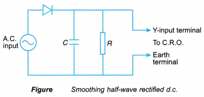
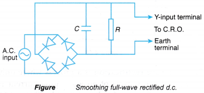
- Figure shows the smoothing circuit for a full-wave rectified d.c.
- Figure shows the graphs of output voltage against time for a smoothed half-wave rectified d.c. and full-wave rectified d.c.
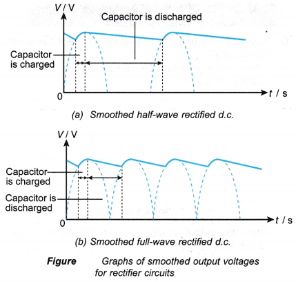
- The charging and discharging process of the capacitor reduces the ripple of the waves.
Half Wave and Full Wave Rectifier Experiment
1. Aims:
A. To build a half-wave rectifier circuit and a full-wave rectifier circuit.
B. To observe half-wave rectification and full-wave rectification
Materials: Diodes, resistor, connecting wires
Apparatus: A.C. power supply, C.R.O.
Method: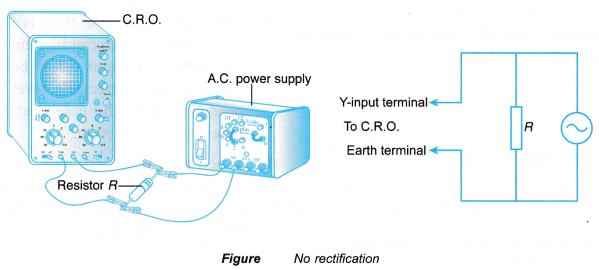
- The apparatus is set up as shown in Figure. The setting of the C.R.O. is adjusted until a suitable trace, about four complete waves, is displayed on the screen.
- A half-wave rectifier circuit is made by connecting a diode in series with resistor R as shown in Figure. The trace displayed on the screen is observed and sketched.
- A full-wave rectifier is made by connecting four diodes as shown in Figure. The trace displayed on the screen is observed and sketched.
Observations:

Discussion:
- Half-wave rectification:
(a) Achieved with only one diode
(b) A pulsating current is produced, where the diode only lets the current flow through resistor R for every half-cycle - Full-wave rectification:
(a) Achieved with four diodes
(b) A continuous current is produced, where one pair of diodes are conducting in the first half-cycle and the other pair of diodes are conducting in the second half-cycle
2. Aim: To observe the effect of putting a capacitor in a half-wave rectifier circuit and a full-wave rectifier circuit
Materials: Diodes, resistor, capacitor, connecting wires
Apparatus: A.C. power supply, C.R.O.
Method:
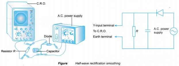
- The apparatus is set up as shown in Figure. The same setting of the C.R.O. as in above experiment is used.
- The trace on the screen is observed and sketched. The observation is compared with the observation in step 2 of above experiment.
- A capacitor is connected to the full-wave rectifier circuit as shown in Figure.
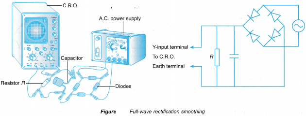
- The trace displayed on the screen is observed and sketched. The observation is compared with the observation in step 3 of above experiment.
Observations:
Discussion:
When a capacitor is connected in a rectifier circuit, the ripple of the waves is reduced where the current is smoothed.
The smoothing capacitor in the rectifier circuit is used to produce a steady d.c. from a rectified a.c.
