What is the electromagnetic induction?
Induced E.M.F. and Induced Current
- Figure shows an induction cooker. During cooking, only the frying pan is heated up. The surface of the cooker is not heated. How is this made possible?
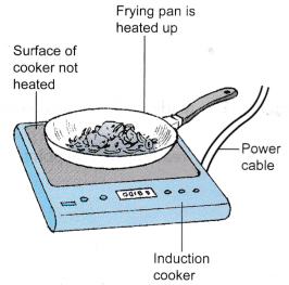
- The induction cooker uses a magnetic field to produce eddy currents in the metal frying pan by a process known as electromagnetic induction. The flow of eddy currents in the frying pan produces heat.
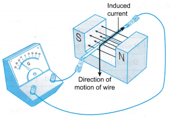
- In Figure, a copper rod is released so that it falls in the magnetic field between a pair of magnets. It is found that the pointer of the centre zero galvanometer shows a deflection while the rod is moving between the magnets. The pointer then returns to its original zero position.
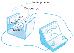
- This shows that an electromagnetic force (em.f) is induced across the copper rod while it is moving across a magnetic field. The induced e.m.f. causes a current to flow in the copper rod.
- The flow chart below summarises the three steps in the production of an induced current.

People also ask
- What is alternating current and direct current?
- What is the Working Principle of AC Generator?
- What is the Working Principle of DC Generator?
- What is the Principle of DC Motor?
- What is magnetic force on a current carrying conductor?
- What is the Meaning of Magnetic Force?
- What factors affect the strength of an electromagnet?
- What is the Magnetic Field?
- What Is Magnetic Effect Of Electric Current?
- Oersted Experiment on Magnetic Effect of Current
- How do you Determine the Direction of the Magnetic Field?
What is Faraday’s law?
The Magnitude of the Induced Current: Faraday’s Law
- Faraday’s law states that the magnitude of the induced e.m.f. is directly proportional to the rate of change of magnetic flux or the rate of cutting of the magnetic flux.
- For the straight wire, the induced e.m.f. can be increased by:
(a) Increasing the speed of the motion
(b) Increasing the strength of the magnetic field - For the solenoid, the induced e.m.f. can be increased by:
(a) Increasing the speed of the relative motion
(b) Increasing the number of turns
(c) Using a stronger magnetic field - The magnitude of the induced current depends on:
(a) The magnitude of the induced e.m.f.
(b) The resistance of the circuit
The relationships between the induced current and the factors affecting it are summarized in Table.Manipulated variable Responding variable Fixed variables Speed of magnet is increased Induced current increases Number of turns, strength of magnet, resistance of circuit Number of turns is increased Induced current increases Speed of magnet, strength of magnet, resistance of circuit Strength of magnet is increased Induced current increases Speed of magnet, number of turns, resistance of circuit Resistance of the circuit is increased Induced current decreases Speed of magnet, number of turns, strength of magnet
Induced E.M.F. and Induced Current in a Straight Conductor
- When a wire moves and cuts magnetic field lines (or magnetic flux), an e.m.f. is induced across the wire.
- Electromagnetic induction Is the production of an e.m.f. across a conductor when it cuts magnetic flux.
- If the wire is in a complete circuit, the induced e.m.f. will cause an induced current to flow.
- Figure shows a direction of motion of the wire that will produce an induced current.
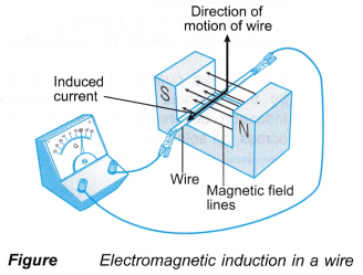
- The direction of the induced current can be determined using Fleming’s right hand rule.
- The following steps are used, as shown in Figure (a).
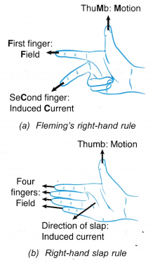 (a) Point the first finger of the right hand in the direction of the magnetic field from the North pole towards the South pole.
(b) Rotate the right hand until the thumb points in the direction of the motion.
(c) The second finger will show the direction of the induced current. - Another rule that can be used is the right-hand slap rule, as shown in Figure (b).
(a) Point the four fingers of the right hand in the direction of the field.
(b) Rotate your hand until the thumb points in the direction of the motion.
(c) Do a slapping action. The direction of the slap is the direction of the induced current. - Figure shows the change in the direction of the induced current when the direction of motion is reversed.
What is Lenz’s law of electromagnetic induction?
Induced E.M.F. and Induced Current in a Solenoid:
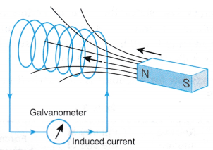
- When a bar magnet is moved towards a solenoid, the magnetic flux moves together with the magnet and cuts the windings of the solenoid.
- An e.m.f. is induced in the solenoid as shown in Figure.
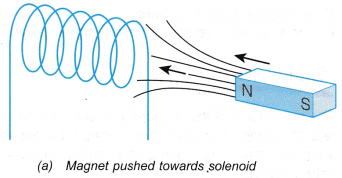
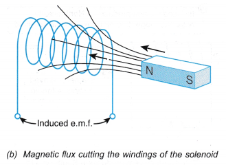
- Electromagnetic induction can also be defined as the production of an e.m.f. across a solenoid when the windings of the solenoid are cut by magnetic flux.
- If the ends of the solenoid are connected to a sensitive centre-zero galvanometer, the deflection of the pointer will show that an induced current flows in the solenoid, as shown in Figure.
- Lenz’s law is used to determine the polarity of the ends of the solenoid facing the magnet. The right-hand grip rule is then used to determine the direction of the induced current in the solenoid.
- Lenz’s law states that the direction of the induced current is such that the motion producing it will be opposed. The use of Lenz’s law is illustrated in Figure.
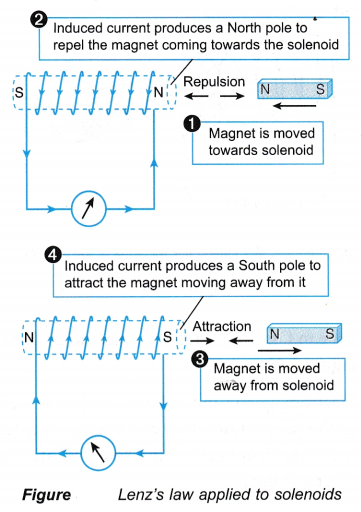
- Lenz’s law for solenoids is summarised in Table.
Relative motion between magnet and solenoid Polarity at the end of the solenoid facing the magnet Force between solenoid and magnet Towards each other Same polarity as the magnet Repulsion Away from each other Opposite polarity as the magnet Attraction - Lenz’s law is an example of the principle of conservation of energy. When the magnet or solenoid is moved against the opposing force, work is done. Therefore, mechanical energy is converted to electrical energy.
Electromagnetic Induction Examples
- Figure shows the direction of the induced current in a wire.
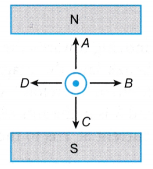
In which direction did the wire move to produce the induced current?
Solution:
Using Fleming’s right-hand rule or the right-hand slap rule, the direction of motion of the wire is D. - Figure shows a bar magnet falling towards a solenoid.
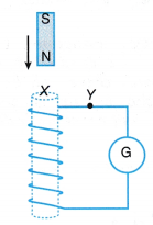
What is the polarity at X and the direction of the current at Y?
Solution:
The magnet is moving towards the solenoid. According to Lenz’s law, the magnet and solenoid must repel each other. Therefore, X is a North pole. The current at end X is in the anti-clockwise direction. Therefore, the current at Y is to the left.
Factors Affecting the Magnitude of the Induced Current Experiment
Aim: To study the factors that affect the magnitude of the induced current.
Materials: Two solenoids with 600 and 1200 turns respectively, two bar magnets, connecting wires, rubber bands
Apparatus: Sensitive centre-zero galvanometer
Method: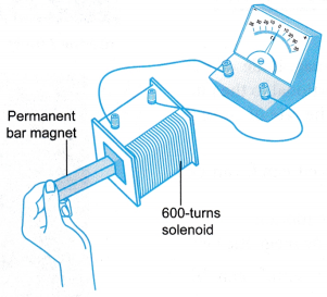
- The apparatus is set up as shown in Figure.
- A bar magnet is pushed slowly into the solenoid of 600 turns. The maximum reading of the galvanometer is recorded.
- The bar magnet is pushed quickly into the solenoid of 600 turns. The maximum reading of the galvanometer is recorded.
- The bar magnet is pushed slowly into the solenoid of 1200 turns. The maximum reading of the galvanometer is recorded.
- Rubber bands is used to tie two bar magnets together with like poles side by side.
- The two magnets are pushed slowly into the solenoid of 600 turns. The maximum reading of the galvanometer is recorded.
Observations:
| Step taken | Number of bar magnets | Speed of magnet | Number of turns of solenoid | Maximum reading of galvanometer |
| Step 2 | 1 | Slow | 600 | 16 |
| Step 3 | 1 | Fast | 600 | 30 |
| Step 4 | 1 | Slow | 1200 | 32 |
| Step 6 | 2 | Slow | 600 | 28 |
Discussion:
- The reading of the galvanometer is proportional to the induced current.
- By comparing the observations in steps 2 and 3, the magnitude of the induced current increases when the speed of the magnet is increased.
- By comparing the observations in steps 2 and 4, the magnitude of the induced current increases when the number of turns of the solenoid is increased.
- Two bar magnets with like poles side by side produce a stronger magnetic field. By comparing the observations of steps 2 and 6, the magnitude of the induced current increases when the strength of the magnetic field is increased.
Conclusion:
The magnitude of the induced current in a solenoid increases when the speed of the magnet, the number of turns of the solenoid or strength of the magnetic field is increased.
Electromagnetic Induction Applications
Applications of Electromagnetic Induction:
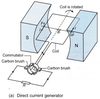
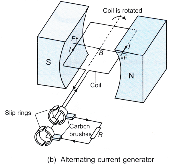
- The direct current generator and the alternating current generator make use of electromagnetic induction to produce an output voltage.
- The coil is rotated by an external force and cuts the magnetic flux.
- An alternating e.m.f. is induced in the coil.
- In the direct current generator, a direct current output is obtained by using a split-ring commutator. In the alternating current generator, two slip rings are used to obtain an alternating current output.
Figure and Table compares the direct current generator and the alternating current generator.
| Direct current generator | Alternating current generator |
| A coil of many turns rotated by an external force in a magnetic field produced by permanent magnets. | |
| Uses electromagnetic induction to generate an e.m.f. in the coil. | |
| Ends of the coil connected to a split-ring commutator. | Ends of the coil connected to two slip rings. |
| The two halves of the split-ring commutator exchange contact with the carbon brushes every half rotation. | Each slip ring is always in contact with the same carbon brush. |
Output current flows in one direction through load resistance, R. | Output current through load flows to and fro in opposite directions j resistance, R.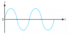 |
| |
Electromagnetic Induction Experiment
Aim: To observe electromagnetic induction in
A. a straight wire B. a solenoid
A. Electromagnetic Induction in a Straight Wire
Materials: Copper rod with bare ends
Apparatus: Magnadur magnets, connecting wires with crocodile clips, sensitive centre-zero galvanometer
Method: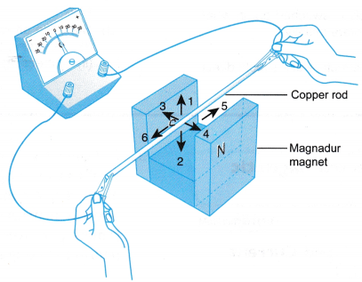
- The apparatus is set up as shown in Figure.
- The copper rod is held stationary between the poles of the magnet. The reading of the galvanometer is observed.
- The rod is moved quickly in Direction 1 as shown in Figure. The reading of the pointer of the galvanometer is observed.
- Step 3 is repeated for directions 2, 3, 4, 5 and 6.
Observations: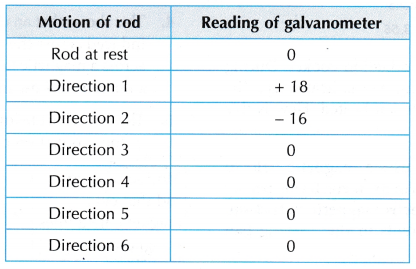
Discussion:
- The magnetic field lines are horizontal lines from the North pole to the South pole.
- Directions 3, 4, 5 and 6 are directions of motion where the copper rod moves along the magnetic field lines and does not cut the lines.
- Directions 1 and 2 are directions of motion where the copper rod cuts across the magnetic field lines.
- An electric current is detected by the galvanometer when its pointer shows a deflection.
- A current is produced in the copper rod when it is moved to cut across the magnetic field lines.
B. Electromagnetic Induction in a Solenoid
Materials: Solenoid with 600 turns
Apparatus: Bar magnet, connecting wires, sensitive centre-zero galvanometer
Method: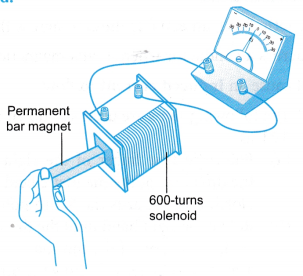
- The apparatus is set up as shown in Figure.
- The solenoid is kept stationary. The reading of the galvanometer is observed for each of the following actions:
(a) The bar magnet is pushed into the solenoid
(b) The bar magnet is held stationary in the solenoid
(c) The bar magnet is pulled out of the solenoid - The bar magnet is held stationary. The reading of the galvanometer is observed for each of the following actions:
(a) The solenoid is pushed towards the bar magnet
(b) The solenoid is pulled away from the bar magnet
Observations:
Discussion:
- The permanent magnet produces a magnetic field in the region around it. When the magnet is moved, the magnetic field moves together with it.
- When the magnet is moved towards and into the solenoid, the magnetic field lines cut the solenoid.
- The galvanometer showed a positive reading when the magnet and solenoid were coming closer to each other. This shows that a current was produced in the solenoid in a certain direction.
- When the magnet is moved out of the solenoid and away from it, the magnetic field lines again cut the solenoid.
- The galvanometer showed a negative reading when the magnet and solenoid were moving further away from each other. A current was produced in the solenoid in the opposite direction.
- A current is induced in a solenoid when there is relative motion between the solenoid and a magnet.
Conclusion:
Current is induced in a straight conductor when it moves and cuts the magnetic field lines. Current is induced in a solenoid when there is relative motion between the solenoid and a magnet.

