What are Concave and Convex Mirrors?
We are used to plane mirrors. But, when they are curved, they produce images that are different from those formed by plane mirrors. Common examples of curved mirrors stainless steel spoons, ladles, vessels with round bases, car mirrors, shaving and hub caps of car wheels. These curved objects have two types of reflecting surfaces one that bulges out to form a convex surface, and one that curves inwards to concave surface. The first one is called a convex mirror and the latter is a concave mirror.
- A curved mirror is actually a mirror with a curved reflective surface. A curved mirror has the same shape as a section of a large sphere as shown in Figure.
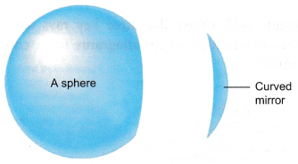
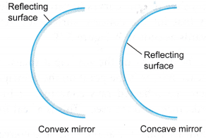
- If the outside surface of the section reflects, the mirror is a convex mirror. If the inside surface reflects, the mirror is a concave mirror.
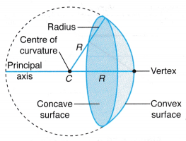
- The principal axis of a curved mirror is the line passing through its vertex, P and the centre of curvature, C.
- The centre of curvature, C of a curved mirror is the centre of the sphere that forms the curved mirror.
- The radius of curvature, R of a curved mirror is the radius of the sphere.
- A concave mirror curves inwards. Parallel light rays that hit the concave surface are reflected inwards as shown in Figure.
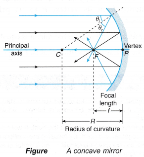
- The focal point or the principal focus, F of a concave mirror is the point on the principal axis where the reflected rays converge, or in other words, meet and intersect. This is a real focus.
- A concave mirror is also known as a converging mirror.
- A convex mirror curves outwards. Parallel light rays that hit the convex surface are reflected outwards as shown in Figure.
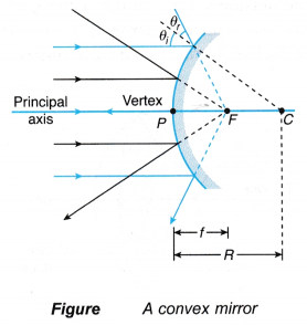
- The focal point, F of a convex mirror is the point on the principal axis where the reflected rays diverge, or in other words, appear to spread out from behind the mirror. This is a virtual focus.
- A convex mirror is also known as a diverging mirror.
- The focal length, f of a curved mirror is the distance from its vertex, P to its principal focus, F.
The focal length of a curved mirror is equal to half of the radius of curvature, that is = R/2
People also ask
- What is Reflection of Light?
- What is the Law of Reflection of Light?
- Application of Reflection of Light in Daily Life
- What do you mean by Total Internal Reflection?
- Application of Reflection of Light in Daily Life
- Applications of Total Internal Reflection
- Image Reflection by a Plane Mirror
- Which Type of Image is Formed by a Plane Mirror?
- Is an Image formed by Reflection Real or Virtual
- Reflection of Light from Spherical Mirror
- What are Concave and Convex Mirrors?
- How is Focal Length related to Radius of Curvature?
- How is the Image Formed by a Spherical Mirror?
Uses of Curved Mirrors
Convex mirrors make things look smaller but you can see a lot more of the surroundings.
In other words, they give you a wider range of view. Some uses of convex mirrors are given below.
• As car wing mirrors, to see through a wide angle behind the car.
• In supermarkets and big shops to look out for shoplifters.
• In buses, so that the driver can view the whole bus.
When objects are kept very close to a concave mirror, objects look larger. This makes concave mirrors useful for the following applications:
• As shaving mirrors or while putting on make-up.
• As a dentist’s mirror for examination.
Concave mirrors can also focus a parallel beam of light to a point. This property is used in solar-powered projects where they reflect the heat rays of the sun so that the rays are concentrated onto a smaller area.
How do you Draw a Ray Diagram for Concave and Convex Mirrors?
- The characteristics of the images formed by curved mirrors can be determined by drawing ray diagrams using three key rays as described:
(a) A parallel ray (ray P) that is incident along a path parallel to the principal axis and is reflected through (or appears to go through) the focal point.
(b) A chief ray (ray C) or radial ray is the ray that incidents through the centre of curvature, C of the curved mirror. Since ray C is incident at normal to the surface of the mirror, it is reflected back along its incident path through point C.
(c) A focal ray (ray F) is the ray that passes through (or appears to go through) the focal point and is reflected parallel to the axis. - Figure shows the three key rays used in the construction of ray diagrams for a concave mirror.
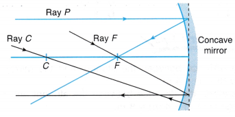
- The characteristics of the images formed by curved mirrors can be determined by drawing ray diagrams using three key rays as described:
- Figure shows the three key rays used in the construction of ray diagrams for a convex mirror.
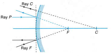
- For both concave and convex, mirrors, ray P and ray F can be reversed to travel back along the same path. This property is known as the reversibility of light.
- The point where any of the two construction lines cross or intersect is the position of the image formed by the curved mirrors.
Steps for Drawing Ray Diagrams
- The following steps are used to draw a ray diagram for a concave mirror.
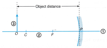
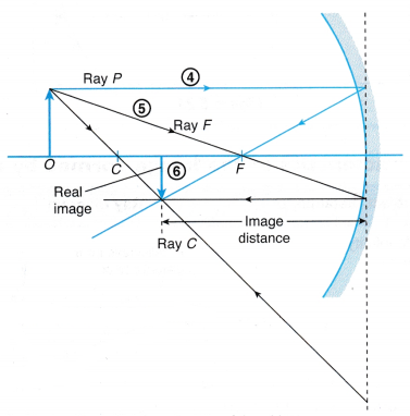
- Step 1: Draw a straight line as the principal axis, curved line as the curved mirror and dotted vertical line at vertex P as the construction line for the curved mirror.
- Step 2: Mark the positions of F and C on the axis with CF = FP.
- Step 3: Draw an arrow as the object standing upright on the axis at a given distance.
- Step 4: Draw ray P coming from the top of the object.
- Step 5: Draw ray F coming from the top of the object. Note that you can also use ray C coming from the top of the object. The top of the image is where any two of the reflected rays meet again after the reflection.
- Step 6: Draw the image with its tail on the axis. The head is the point where the two reflected rays meet.
- The characteristics of the image formed can be:
(a) real or virtual,
(b) inverted or upright,
(c) magnified, diminished or of the same size. - For a convex mirror, the ray diagram is as shown in Figure.
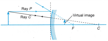
- Dotted lines are used for extending the rays backward to locate the virtual image behind the surface of the mirror.
- A virtual image is also drawn using a dotted line with an arrow.
- Ray diagrams showing the images formed by a concave mirror and a convex mirror when the object is placed at different distances are shown in the next section. The characteristics of the image formed are stated in each case.
