CBSE Sample Papers for Class 12 Physics Paper 6 are part of CBSE Sample Papers for Class 12 Physics. Here we have given CBSE Sample Papers for Class 12 Physics Paper 6.
CBSE Sample Papers for Class 12 Physics Paper 6
| Board | CBSE |
| Class | XII |
| Subject | Physics |
| Sample Paper Set | Paper 6 |
| Category | CBSE Sample Papers |
Students who are going to appear for CBSE Class 12 Examinations are advised to practice the CBSE sample papers given here which is designed as per the latest Syllabus and marking scheme as prescribed by the CBSE is given here. Paper 6 of Solved CBSE Sample Paper for Class 12 Physics is given below with free PDF download solutions.
Time Allowed : 3 Hours
Max. Marks : 70
- All questions are compulsory. There are 26 questions in all.
- This question paper has five sections: Section A, Section B, Section C, Section D and Section E.
- Section A contains five questions of 1 mark each. Section B contains five questions of 2 marks each. Section C contains twelve questions of 3 marks each. Section D contains one value based question of 4 marks and Section E contains three questions of 5 marks each.
- There is no overall choice. However, an internal choice has been provided in 1 question of 2 marks, 1 question of 3 marks and all the 3 questions of 5 marks weightage. You have to attempt only 1 of the choices in such questions.
- You may use the following values of physical constants wherever necessary :
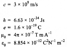
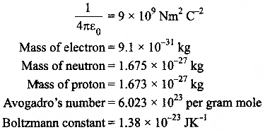
Questions
SECTION : A
Question 1.
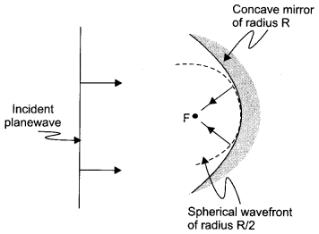
Draw the shape of the wavefront coming out of a convex lens when a plane wave is incident on it.
Question 2.
Why does bluish colour predominate in a clear sky?
Question 3.
Write the condition under which an electron will move undeflected in the presence of crossed electric and magnetic fields.
Question 4.
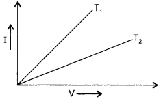
I-V graph for a metallic wire at two different temperature, T1 and T2 is as shown in the figure. Which of the two temperatures is lower and why?
Question 5.
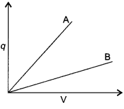
The given graph shows variation of charge ‘q’ versus potential difference ‘V’ for two capacitors C1 and C2. Both the capacitors q have same plate separation but plate area of C2 is greater than that of C1 Which line (A or B) corresponds to C1 and why?
SECTION : B
Question 6.
Calculate the shortest wavelength in the Balmer series of hydrogen atom. In which region (infra-red, visible, ultraviolet) of hydrogen spectrum does this wavelength lie?
Question 7.
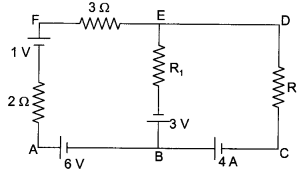
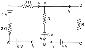
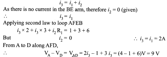
Use Kirchhoff’s rules to determine the potential difference between the points A and D when no current flows in the arm BE of the electric network shown in the figure.
Question 8.
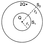
A sphere of radius r1 encloses a net charge Q. If there is another concentric sphere S2 of radius r2 (r2 > r1) enclosing charge 2Q, find the ratio of the electric flux through S1 and S2. How will the electric flux through sphere S1 change if a medium of dielectric constant K is introduced in the space inside S2 in place of air ?
Question 9.
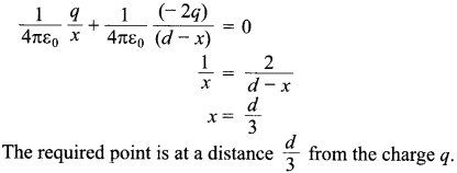
Two point charges q and – 2q are kept ‘d’ distance apart. Find the location of the point relative to charge ‘q’ at which potential due to this system of charges is zero.
OR
An electric dipole is placed in a uniform electric field \(\vec { E } \) with its dipole moment \(\vec { P } \) parallel to the field. Find
- the work done in turning the dipole till its dipole moment points in the direction opposite to E.
- the orientation of the dipole for which the torque acting on it becomes maximum.
Question 10.
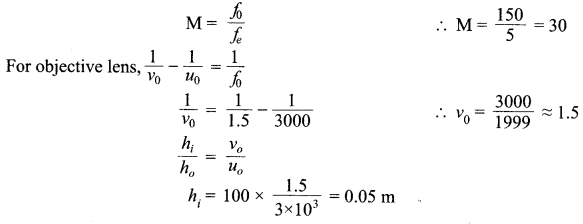
You are given two converging lenses of focal lengths 1.25 cm and 5 cm to design a compound microscope. If it is desired to have a magnification of 30, find out the separation between the objective and the eyepiece
OR
A small telescope has an objective lens of focal length 150 cm and eyepiece of focal length 5 cm. What is the magnifying power of the telescope for viewing distant objects in normal adjustment? If this telescope is used to view a 100 m tall tower 3 km away, what is the height of the image of the tower formed by the objective lens ?
SECTION : C
Question 11.
- How is an electromagnet different from a permanent magnet?
- Write two properties of a material which make it suitable for making electromagnets.
Question 12.
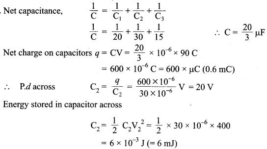
Calculate the potential difference and the energy stored in the capacitor C2 in the circuit shown in the figure. Given potential at A is 90 V, C1 = 20 μF, C2 = 30 μF and C3 = 15 μF.

Question 13.
An electron is revolving around the nucleus with a constant speed of 2.5 x 10⁸ m/s. Find the de Broglie wavelength associated with it.
Question 14.
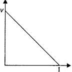
Distinguish between emf (ε) and terminal voltage (V) of a cell having internal resistance ‘r’. Draw a plot showing the variation of terminal voltage (V) vs the current (I) drawn from the cell. Using this plot, how does one determine the internal resistance of the cell?
Question 15.
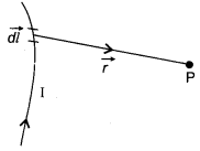
(i) State Biot-Savart law in vector form expressing the magnetic field due to an element \(\vec { dl }\) carrying current I at a distance \(\vec { r }\) from the element.
(ii) Write the expression for the magnitude of the magnetic field at the centre of a circular loop of radius r carrying a steady current I. Draw the field lines due to the current loop.
Question 16.
- Define the term threshold frequency.
- Plot a graph showing the variation of photoelectric current as a function of anode potential for two light beams of same frequency but of different intensities, I1 and I2 (I2 > I1).
Question 17.
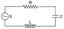
The figure shows a series LCR circuit connected to a variable frequency 250 V source with L = 80 mH, C = 50 μF and R = 60 Ω.
Determine :
- the source frequency which derives the circuit in resonance
- the quality factor (Q) of the circuit.
Question 18.
- Write the truth table for an OR gate and draw its logic symbol.
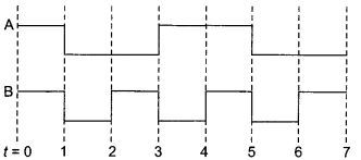
- The input waveforms A and B, shown below, are fed to an AND gate. Find the output waveform.
Question 19.
(a) Unpolarised light of intensity IQ passes through two polaroids P1 and P2 such that pass axis of P2 makes an angle θ with the pass axis of P1. Plot a graph showing the variation of intensity of light transmitted through P2 as the angle varies from zero to 180°.
(b) A third polaroid P3 is placed between P1 and P2 with pass axis of P3 making an angle with that of P1. If I1, I2 and I3 represent the intensities of light transmitted by P1 ,P2 and P3, determine the values of angle and for which I1 = I2 = I3.
Question 20.
(a) State the underlying principle of a potentiometer. Why is it necessary to
- use a long wire
- have uniform area of cross-section of the wire and
- use a driving cell whose emf is taken to be greater than the emfs of the primary cells?
(b) In a potentiometer experiment, if the area of the cross-section of the wire increases uniformly from one end to the other, draw a graph showing how potential gradient would vary as the length of the wire increases from one end.
Question 21.
- How is a toroid different from a solenoid?
- Use Ampere’s circuital law to obtain the magnetic field inside a toroid.
- Show that in an ideal toroid, the magnetic field
- inside the toroid and
- outside the toroid at any point in the open space is zero.
OR
Derive an expression for the magnetic moment (\(\vec { \mu } \)) of an electron revolving around the nucleus in terms of its angular momentum ( \(\vec { L } \) ). What is the direction of the magnetic moment of the electron with respect to its angular momentum?
Question 22.
State two properties of electromagnetic waves. How can we show that em waves carry momentum?
SECTION : D
Question 23.
Amab was talking on his mobile to his friend for a long time. After his conversation was over, his sister Anita advised him that if his conversation was of such a long duration, it would be better to talk through a land line.
- Why is it considered harmful to use a mobile phone for a long duration?
- Which values are reflected in the advice of his sister Anita?
- A message signal of frequency 10 kHz is superposed to modulate a carrier wave of frequency 1 MHz. Determine the sidebands produced.
SECTION : E
Question 24.
(a) Draw the circuit arrangement for studying V-I characteristics of a p-n junction diode in
- forward and
- reverse bias. Briefly explain how the typical V-I characteristics of a diode are obtained and draw these characteristics.
(b) With the help of necessary circuit diagram explain the working of a photo diode used for detecting optical signals.
OR
(a) Draw the circuit diagram of an n-p-n transistor with emitter- base junction forward biased and collector-base junction reverse biased. Describe briefly how the motion of charge carriers in the transistor constitutes the emitter current (IE), the base current (IB) and the collector current (Ic). Hence, deduce the relation IE = IB + IC.
(b) Explain with the help of circuit diagram how a transistor works as an amplifier.
Question 25.
(a) Draw a schematic arrangement for winding of primary and secondary coil in a transformer when the two coils are wound on top of each other. State the underlying principle of a transformer and obtain the expression for the ratio of secondary to primary voltage in terms of the
- number of secondary and primary windings and
- primary and secondary currents.
(b) Write the main assumption involved in deriving the above relations. Write any two reasons due to which energy losses may occur in actual transformers.
OR
A metallic rod of length l and resistance R is rotated with a frequency v, with one end hinged at the centre and the other end at the circumference of a circular metallic ring of radius l, about an axis passing through the centre and perpendicular to the plane of the ring. A constant and uniform magnetic field B parallel to the axis is present everywhere.
- Derive the expression for the induced emf and the current in the rod.
- Due to the presence of the current in the rod and of the magnetic field, find the expression for the magnitude and direction of the force acting on this rod.
- Hence obtain the expression for the power required to rotate the rod.
Question 26.
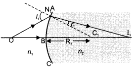
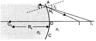
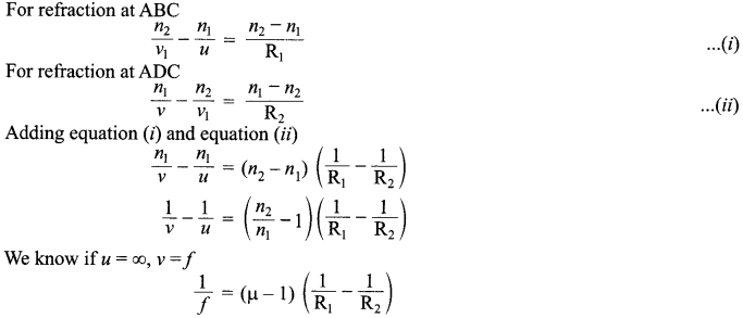
(a) A point object is placed in front of a double convex lens (of refractive index n = n1 / n2 with respect to air) with its spherical faces of radii of curvature R1 and R2. Show the path of rays due to refraction at first and subsequently at the second surface to obtain the formation of the real image of the object. Hence obtain the lens-maker’s formula for a thin lens.
(b) A double convex lens having both faces of the same radius of curvature has refractive index 1.55. Find out the radius of curvature of the lens required to get the focal length of 20 cm.
OR
(a) Draw a labelled ray diagram showing the image formation of a distant object by a refracting telescope. Deduce the expression for its magnifying power when the final image is formed at infinity.
(b) The sum of focal lengths of the two lenses of a refracting telescope is 105 cm. The focal length of one lens is 20 times that of the other. Determine the total magnification of the telescope when the final image is formed at infinity
Answers
SECTION : A
Answer 1.
Answer 2.
As per Rayleigh scattering law, the amount of scattering varies inversely with the fourth power of wavelength. Scattering of the blue colour is maximum due to its shorter wavelength.
Answer 3.
v = E/B where v is speed is of electron.
Alternatively,
![]()
Answer 4.
In Fig., Slope = 1/ Resistance
Here slope of T1 is greater than T2 therefore resistance of T1 is lesser than T2. Resistance of a material decreases with decrease in temperature. Thus, T1 temperature is lower than T2.
Answer 5.
Line B, Since slope (q / V) of B is lesser than that of A.
SECTION : B
Answer 6.

3646 Å = 364.6 nm lies in ultraviolet region of spectrum.
Answer 7.
According to Kirchhoff’s Junction law at B
Answer 8.

No change in flux through S1 with dielectric medium inside the sphere S2
Answer 9.

Let P be the required point at a distance x from charge q
OR
(i) We have

(ii)
![]()
Answer 10.

OR
SECTION : C
Answer 11.
(a) An electromagnet consists of a core made of a ferromagnetic material placed inside a solenoid. It behaves like a strong magnet when current flows through the solenoid and effectively loses its magnetism when the current is switched off. A permanent magnet is also made up of a ferromagnetic material but it retains its magnetism at room temperature for a long time after being magnetized once.
(b)
- High permeability
- Low retentivity
- Low coercivity (Any two)
Answer 12.
Answer 13.

Answer 14.
Difference between emf (ε) and terminal voltage (V)

(Any one) or any other relevant difference
Negative of slope gives internal resistance.
Answer 15.
(i) According to Biot Savart’s law, the magnetic field due to an element \(\vec { dl }\)carrying current I at a point with position P vector \(\vec { r }\) is given by

(ii)
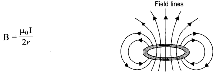
Answer 16.
(a) The threshold frequency for a given photosensitive surface is the minimum value of frequency of incident light that can cause photoemission from it.
(b) The required plot is as shown here :
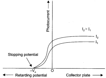
Answer 17.
(i)

(ii)
![]()
Answer 18.
(i) Truth table for an OR gate

(ii) Output Waveform :
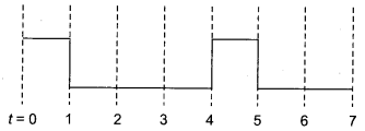
Answer 19.
(a)
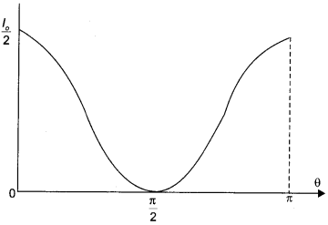
Using I2 = I1 cos2 θ
(b)
I1 = Light transmitted by P1
I3 = Light transmitted by P3 = I1 cos2 β ……..(i)
I2 = Light transmitted by P2 = I1 cos2(θ – β) ……..(ii)
According to question I2 = I3
Substituting the values of I2 and I3 from eqn. (i) and (ii), we get
I3 cos2(θ – β)2 = I1 cos2 β ………..(iii)
Substituting the value of I3 from eqn. (i) in eqn. (iii)
0 – β = 0°
∴ 0 = β
Alternatively
I1 cos2 β . cos2 (θ – β)2 = I1 cos2 β or cos2(θ – β) = 1 = cos 0°
⇒ θ – β = 0
∴ θ = 0° or π
Therefore,
β = 0° or π
Answer 20
(a) Principle of potentiometer :
The potential drop across the length of a steady current carrying wire of uniform cross section is proportional to the length of the wire.
- We use a long wire to have a lower value of potential gradient (i. e. a lower ‘least count’ or greatest sensitivity of the potentiometer).
- If wire has uniform cross-section area then only it has uniform resistance per unit length and then the fall of potential per unit length of the wire will be uniform on passing constant current through it.
- The emf of the driving cell has to be greater than the emf of the primary cells as otherwise no balance point would be obtained.
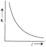
(b) Potential gradient K = V/l
∴ The required graph is as shown.
Answer 21.
(a) Solenoid is a straight coil having uniform number of turns per unit length. A toroid is an endless Solenoid. It is in the form of the hollow sphere, having large number of turns.
(b) For the magnetic field at a point S inside a toroid we have
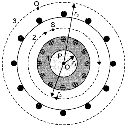
B1B(2πr) = μ0NI
B = μ0NI/2πr
= μ0nI (n = no. of turns per unit length of toroid)
(c) For the loop 1, Ampere’s circuital law gives
B12πr1 = μ0(0) i.e. B1 = 0
Thus the magnetic field, in the open space inside the toroid is zero.
Also at point Q, we have B3(2πr3) =μ0(Ienclosed)
But from the sectional cut, we see that the current coming out of the plane of the paper, is cancelled exactly by the current going into it.
Hence ,
⇒ Ienclosed = 0
∴ B3 = 0
OR
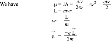
The direction of \(\vec { \mu } \) is opposite to that of \(\vec { L } \) because of the negative charge of the electron and Ampere’s circuital law was put in its generalized form only
![]()
This form gives consistent results for values of B irrespective of which surface is used to calculate it.
Answer 22.
Properties of electromagnetic waves :
- Transverse nature
- Does not get deflected by electric fields or magnetic fields.
- Same speed in vacuum for all waves.
- No material medium required for propagation.
- They get refracted, diffracted and polarised.
Electric charges present on a plane, kept normal to the direction of propagation of an em wave can be set and sustained in motion by the electric and magnetic field of em waves. Thus charge acquire energy and momentum from the em waves.
Em waves have mutually perpendicular oscillating electric and magnetic fields. There is an energy density associated with both the electric and magnetic fields. In general energy per unit volume in an electric and magnetic field is given by:
Energy density in an electric field = y1/2 ε0E2
In a magnetic field, the energy per unit volume is :
Energy density in an magnetic field = 1/2 B2/μ0
So the total energy density associated with an electromagnetic wave is: u =1/2 ε0E2 + 1/2 B2/μ0
SECTION : D
Answer 23.
(a) The ultra high frequency em radiations, continuously emitted by a mobile phone, may harm the system of the human body.
(b) Sister Anita shows
- Concern about her brother
- Awareness about the likely effects of em radiations on human body
- Sense of responsibility (any two)
(c) The side bands are
(vc + vm) and (vc – vm)
OR
(1000+ 10) kHz and (1000-10) kHz
1010 kHz and 990 kHz
SECTION : E
Answer 24.
(a)

The V-I characteristics are obtained by connecting the battery, to the diode, through a potentiometer (or rheostat). The applied voltage to the diode is changed. The values of current, for different values of voltage, are noted and a graph between V and I plotted. The V-I characteristics of a diode have the form shown here.
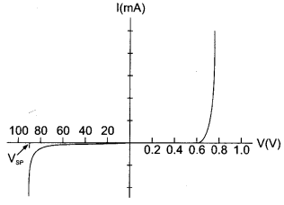
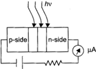
(b) The circuit diagram for the photodiode is shown here. The photodiode is illuminated by optical signal, whose photo energy is greater than the energy gap of the semiconductor used. The electric field at the junction, separates the electrons and holes and thus gives rise to an emf. When an external load is connected, a (photo) current flows through it. The magnitude of this current is proportional to the intensity of light incident on the photodiode.
OR
(a) The circuit diagram is shown here. The emitter-base junction, being forward biased the majority charge carriers (electrons), from the emitter, flow into the base region constituting the emitter current (IE).
The base region, being very thing, only a (very) small fraction, of these charge carriers, swamps the holes present in the base region resulting in a (small) base current (IB).
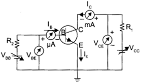
The majority of these charge carriers, are attracted by the (reverse biased) collector. These make up the collector current (Ic).
It is clear, therefore, that IE = Ic + IB.
(b) The circuit diagram of a transistor, working as an amplifier, in its CE mode, is shown here.
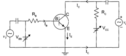
If a small sinusoidal voltage is superimposed on the dc base bias by connecting the source of this signal in series with VBB supply. Then the base current will have sinusoidal variations superposed on the values IB. As a consequence the collector current also will have sinusoidal variation superimposed on the value of Ic producing in turn corresponding change in the output voltage Vo.
Answer 25.
(a)
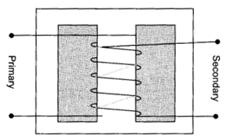
Principle of a transformer :
When alternating current flows through the primary coil, an emf is induced in the neighbouring (secondary) coil.
(i) Let dΦ/dt be the rate of change of flux through each turn of the primary and the secondary

(ii) But for an ideal transformer V1I1 = V2I2

(b) Main assumptions
- The primary resistance and current are small
- The flux linked with the primary and secondary coils is same/there is no leakage of flux from the core.
- Secondary current is small (Any one)
Reason due to which energy loses may occur are:
Flux leakage/resistance of the coils/eddy currents/Hysteresis (Any two)
OR
(a)

(b) Force acting on the rod,
![]()
The external force required to rotate the rod opposes the Lorentz force acting on the rod/ external force acts in the direction opposite to the Lorentz force.
(c)
Power required to rotate the rod
![]()
Answer 26.
(a) (i)
(ii)
(iii)
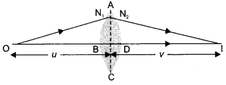
The first refracting surface ABC forms the image I1 of the object O. The image I1 acts as a virtual object for the second refracting surface ADC which forms the real image I as shown in the (ii) diagram.
(b)

OR
(a)
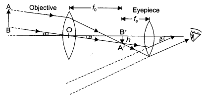

(b)

We hope the CBSE Sample Papers for Class 12 Physics Paper 6 help you. If you have any query regarding CBSE Sample Papers for Class 12 Physics Paper 6, drop a comment below and we will get back to you at the earliest.
