Analysing Interference of Waves
- Figure shows two drops of rain water falling on the surface of a pond, producing two sets of circular waves. When the two sets of waves overlap with each other, they will form an interference pattern.
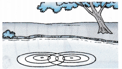
- Interference of waves is a phenomenon that occurs when two separate sets of waves meet to produce a combined effect.
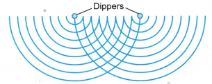
- The two dippers in Figure, which produce a continuous sequence of waves, act as coherent source of waves. Coherent sources of waves produce waves of the same frequency, amplitude and phase difference.
People also ask
- Analysing Reflection of Waves
- Analysing Refraction of Waves
- Analysing Diffraction of Waves
- Analysing Sound Waves
- Analysing Electromagnetic Waves
What is Meant by Superposition of Waves?
Principle of Superposition
- Figure shows two opposing waves passing through each other. When they meet, the waves overlap with each other to form a combined waveform.
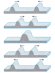
- The principle of superposition states that at any time, the combined waveform of two or more interfering waves is given by the sum of the displacement of the individual waves at each point of the medium.
What is Constructive and Destructive Interference?
Constructive Interference
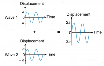
- When interference occurs, the waves either interfere constructively or destructively.
- When the vertical displacements of the two waves are in the same direction as in Figure, constructive interference occurs.
- If the amplitude of each individual wave is a, then the amplitude of the combined wave is 2a.
Destructive Interference
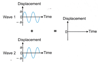
- If a wave with a positive displacement meets another with a negative displacement of the same magnitude, they cancel each other and the combined amplitude becomes zero. Thus the waves undergo destructive interference.
- Figure shows two waves that meet and interfere destructively.
Formula for Interference
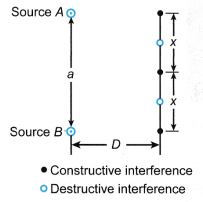 a = Distance between the two coherent sources of waves
x = Distance between two consecutive constructive interferences (or destructive interferences)
D = Perpendicular distance between the two coherent sources of waves and the place where the interference pattern is observed
Figure shows the interference of two coherent sources, A and B.
If the wavelength of the waves is A, then the approximate relationship between A, a, x and D is given by the formula:
Interference of Waves Example Problems with Solutions
- In an experiment using a ripple tank and its accessories, two spherical dippers are placed 6.0 cm apart to form an interference pattern. The perpendicular distance between the dippers and the location where x is measured is 20 cm. If x = 3.0 cm, determine the wavelength of the waves.
Solution:

- Figure shows the interference pattern formed on a screen in a Young’s double-slit experiment using blue light. The distance between the screen and the double slits is 3.0 m. The distance between the slits is 0.30 mm.
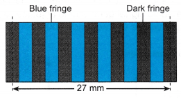
(a) Calculate the wavelength of the blue light.
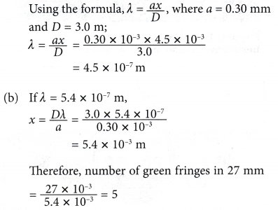
(b) If the blue light is replaced with a green light with a wavelength of 5.4 x 10⁻⁷ m, how many green fringes will be observed in 27 mm?
Solution:
(a) From the diagram, there are 6 blue fringes in 27 mm.
Hence, 6x = 27 mm
x = 4.5 mm
- Two loudspeakers placed 1.5 m apart are connected to an audio signal generator adjusted to a frequency of 600 Hz. When a student walks at a distance of 3.0 m in front of the loudspeakers, he hears 4 consecutive loud sounds through a distance of 3.3 m.
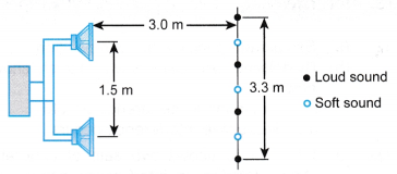
Calculate
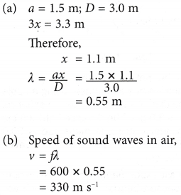
(a) the wavelength of the sound waves.
(b) the speed of the sound waves in air.
Solution:
Interference of Water Waves in Ripple Tank Experiment
Aim: To study the interference pattern of water waves in a ripple tank.
Material: White paper as screen
Apparatus: Ripple tank with its accessories, stroboscope
Method:
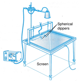
- The ripple tank is arranged as shown in Figure.
- The legs of the ripple tank are adjusted so that the base of the tank is horizontal. The tank is filled with water.
- Two spherical dippers are attached to the vibrating beam so that the bottom of the spheres touch the surface of the water in the ripple tank.
- The speed of the motor is adjusted to produce two sets of waves that can be clearly observed on the screen with the help of a stroboscope.
- The interference pattern formed by the superposition of the two sets of waves is observed.
Observation:
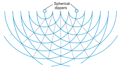 The observed interference pattern is as shown in Figure.
Discussion:
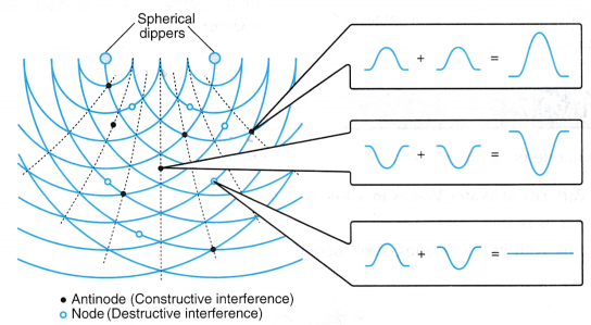
- Figure shows the details of the interference of waves that occurs in the ripple tank.
- The point where a constructive interference occurs is known as an antinode.
- The point where a destructive interference occurs is known as a node.
Interference of Light Experiment
Aim: To study the interference pattern of light.
Material: White paper as screen
Apparatus: Laser pointer, two retort stands with clamps, Young’s double-slit
Method:
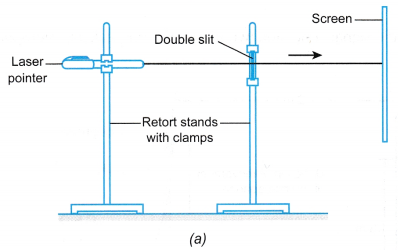
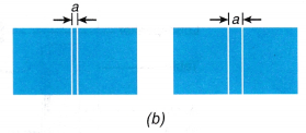
- The apparatus is set up as shown in Figure.
- A laser beam is directed through the double-slit onto the screen.
- The distance and the positions of the laser pointer and double-slit are adjusted until a clear interference pattern of light
- from the laser beam falls on the screen.
- The double-slit is replaced with another double-slit with a bigger separation between the slits. Steps 2 and 3 are repeated.
Observation:
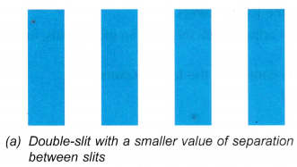
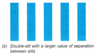
The interference patterns for different widths of the double-slit are shown in Figure.
Discussion:
- The interference of light waves occurs when two sets of coherent light waves emerging from a double-slit overlap and interfere with each other. Historically, this experiment is known as Young’s double-slit experiment.
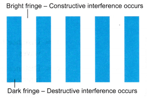
- The interference pattern consists of alternating bright and dark fringes, which correspond to the constructive and destructive interferences respectively.
Interference of Sound Waves Experiment
Aim: To study the interference pattern of sound waves.
Material: A stick
Apparatus: Cathode ray oscilloscope (C.R.O.), audio signal generator, two identical loudspeakers, microphone, table
Method:
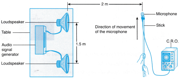
- The apparatus is set up in an open space as shown in Figure.
- The two loudspeakers are adjusted to be about 1.5 m apart and both are connected to the same audio signal generator.
- The audio signal generator is adjusted to a frequency of about 400 Hz.
- A microphone with a long stick is held at about 2 m from the loudspeakers.
- The microphone wire is connected to the C.R.O. that is adjusted to indicate sound signals from the loudspeakers.
- The microphone is moved slowly in a straight line which is parallel to the loudspeakers.
- The trace displayed on the screen of the C.R.O. is observed.
Observation:
- When the C.R.O. displays a wave form with a big amplitude, it indicates that a loud sound is detected.
- The experiment shows that as the microphone is moved along a straight line, alternating loud and weak sounds are detected.
Discussion:
Alternating loud and weak sounds detected by the C.R.O. indicate the occurrence of interference of sound waves.
(a) A loud sound corresponds to the occurrence of constructive interference.
(b) A weak sound corresponds to the occurrence of destructive interference.
